Self-mixing Receiver and Forming Method Thereof

a receiver and self-mixing technology, applied in the field of receivers, can solve the problems of low and achieve the effect of reducing the amount of used inductors, lowering the required circuit area and power dissipation

Inactive Publication Date: 2009-02-05
NAT TAIWAN UNIV
View PDF10 Cites 12 Cited by
  • Summary
  • Abstract
  • Description
  • Claims
  • Application Information

AI Technical Summary

Benefits of technology

[0005]Generally, inductors in standard manufacturing process are planar spiral structure, and inductors approximate a few nano-Henry will occupy over half a circuit area, so that the bulky chip is necessary for installing the inductors. Consequently, to reduce the amount of used inductors will lower the required circuit area and power dissipation.

Problems solved by technology

Consequently, to reduce the amount of used inductors will lower the required circuit area and power dissipation.

Method used


Image

  • Self-mixing Receiver and Forming Method Thereof
  • Self-mixing Receiver and Forming Method Thereof
  • Self-mixing Receiver and Forming Method Thereof

Examples


Embodiment Construction

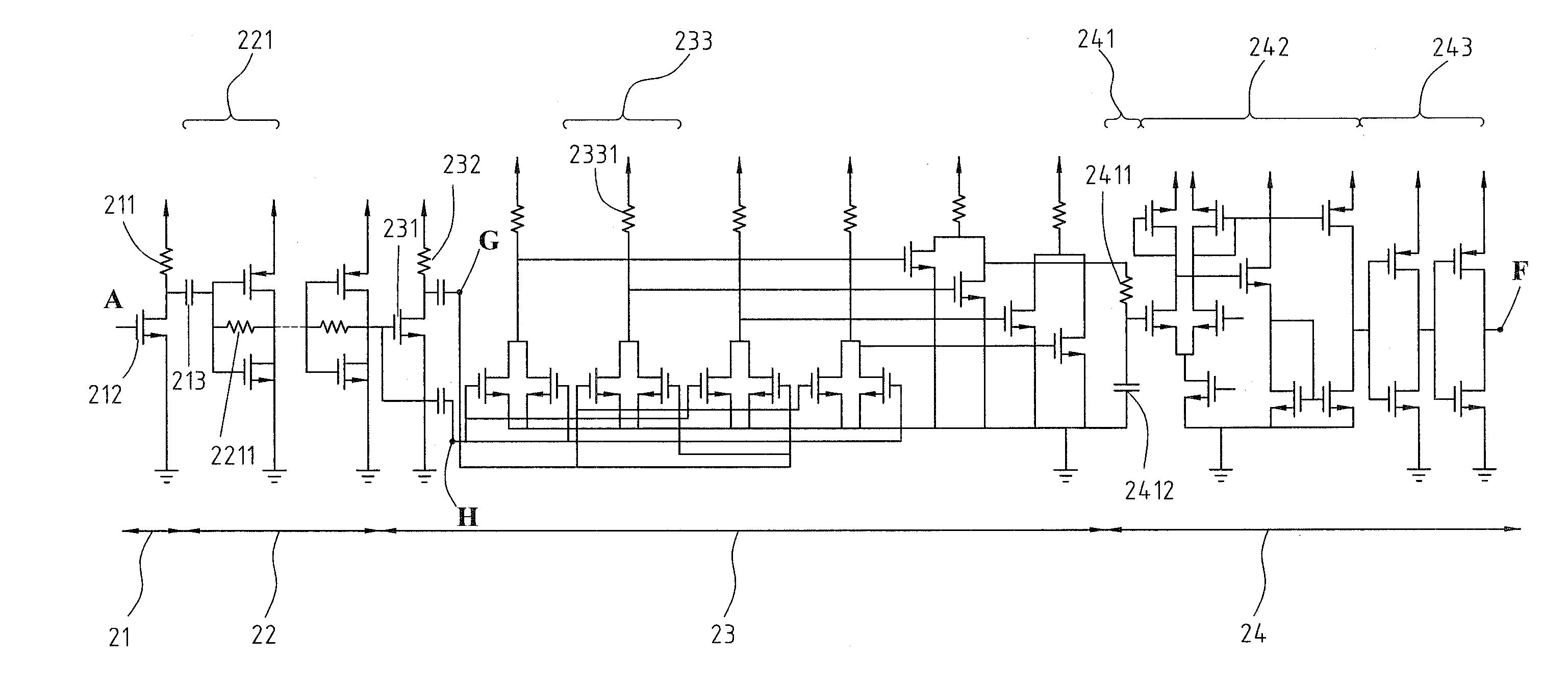
[0027]FIG. 3 illustrated the formation of the self-mixing receiver. As shown in FIG. 3, the self-mixing receiver is a four-cascaded stage architecture to receive electric signals and transmit digital signals. The circuit structure of the self-mixing receiver 2 comprises a high input impedance voltage amplifier 21, a multi-stage amplifier 22, a mixer 23, and a digital output converter 24, wherein the high input impedance voltage amplifier 21 including an input end utilized to be the electric signal receiving terminal B of self-mixing receiver 2. Additionally, the multi-stage amplifier 22 is connected to the output end of high input impedance voltage amplifier 21, and the mixer 23 is connected to the output end C of multi-stage amplifier 22. Besides, the digital output converter 24, connected to the output end D of mixer 23, includes a low pass filter 241, a voltage comparator 242, and a digital inverter 243, wherein the positive input end of voltage comparator 242 connected to the ou...


PUM


Abstract

This invention is primarily a circuit structure of self-mixing receiver, and the methodology of circuit structure is described as follows. The first stage is a high input impedance voltage amplifier utilized to amplify the received RF carrier signal from the antenna. Besides, there are no any inductors required. The second stage is a multi-stage amplifier to amplify the output signal of first stage to rail-to-rail level, which is quite the same with supply voltage. The third stage is a mixer adopted to lower the signal frequency. The fourth stage is a digital output converter, which is proposed to demodulate the electric signals and convert the demodulated signal to digital signal.

Description

FIELD OF THE INVENTION[0001]The present invention relates to a receiver, and more particularly, to a self-mixing receiver and forming method for wireless network system and biomedical wireless communication system.BACKGROUND OF THE INVENTION[0002]A conventional receiver is usually added with external components to receive different kinds of signals effectively. With reference to FIG. 1 to illustrate a super heterodyne receiver 1. The super heterodyne receiver 1 includes a low noise amplifier 11, a mixer 13, a voltage-controlled oscillator 14, and a demodulator 16, and the super heterodyne receiver 1 is added with an image rejection filter 12 and an IF filter 15. Thus, the super heterodyne receiver 1 needs large circuit area and large power dissipation.[0003]To overcome the shortcomings of large circuit area and power dissipation, the method of amplitude-shift keying (ASK) is utilized with envelop detection to lower circuit area and power dissipation. For example, “Direct-conversion ...

Claims


Application Information

Patent Timeline
Patent Type & Authority Applications(United States)
IPC IPC(8): H04L27/06H04L27/04H04L25/34
CPCH04L27/06
Inventor LU, SHEY SHILIN, YU TSOLIAO, FANG REN
Owner NAT TAIWAN UNIV
Why Eureka
Try Eureka