
Cooling system for a vehicle

a technology for cooling systems and vehicles, applied in indirect heat exchangers, machines/engines, light and heating apparatus, etc., can solve the problems of limiting the choice of deign objects, and achieve the effects of reducing production costs, high efficiency, and reducing the weight of heat exchangers

Inactive Publication Date: 2009-02-12
HALLA CLIMATE CONTROL
View PDF17 Cites 8 Cited by
  • Summary
  • Abstract
  • Description
  • Claims
  • Application Information

AI Technical Summary

Benefits of technology

"The present invention provides a cooling system for a vehicle that includes a thin radiator that reduces production costs, enhances heat radiation performance, and reduces energy loss due to a pressure drop of the coolant. The system also includes an optimal design condition for enhancing heat radiation performance in a critical driving mode of a vehicle and reducing a coolant-side pressure drop amount. The design of the radiator is optimized to maintain heat radiation performance while reducing its weight and coolant-side pressure drop amount. The cooling system includes a thermostat for adjusting the coolant flow rate based on the engine temperature, and the coolant flows through the radiator in a turbulent flow region with a high Reynolds number. The system also includes a fin with a specific design for maximizing heat transfer rate and reducing weight. The heat exchange tube is a flat type without a dimple, and the heat exchanger is a cross flow type."

Problems solved by technology

Particularly, there are some limitations in suggesting a preferred deign object of exchanger tubes in a critical operation condition such as alpine regions with many inclines or cold or arctic regions.

Method used


Image

  • Cooling system for a vehicle
  • Cooling system for a vehicle
  • Cooling system for a vehicle

Examples


Embodiment Construction

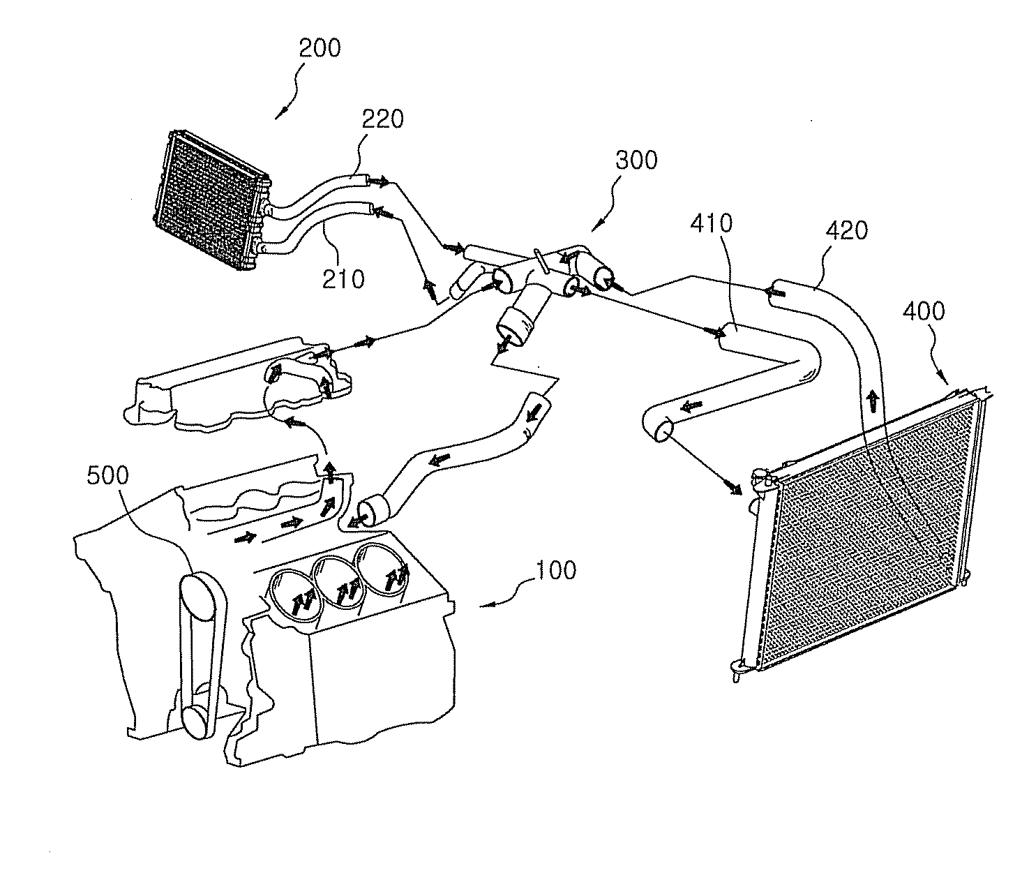
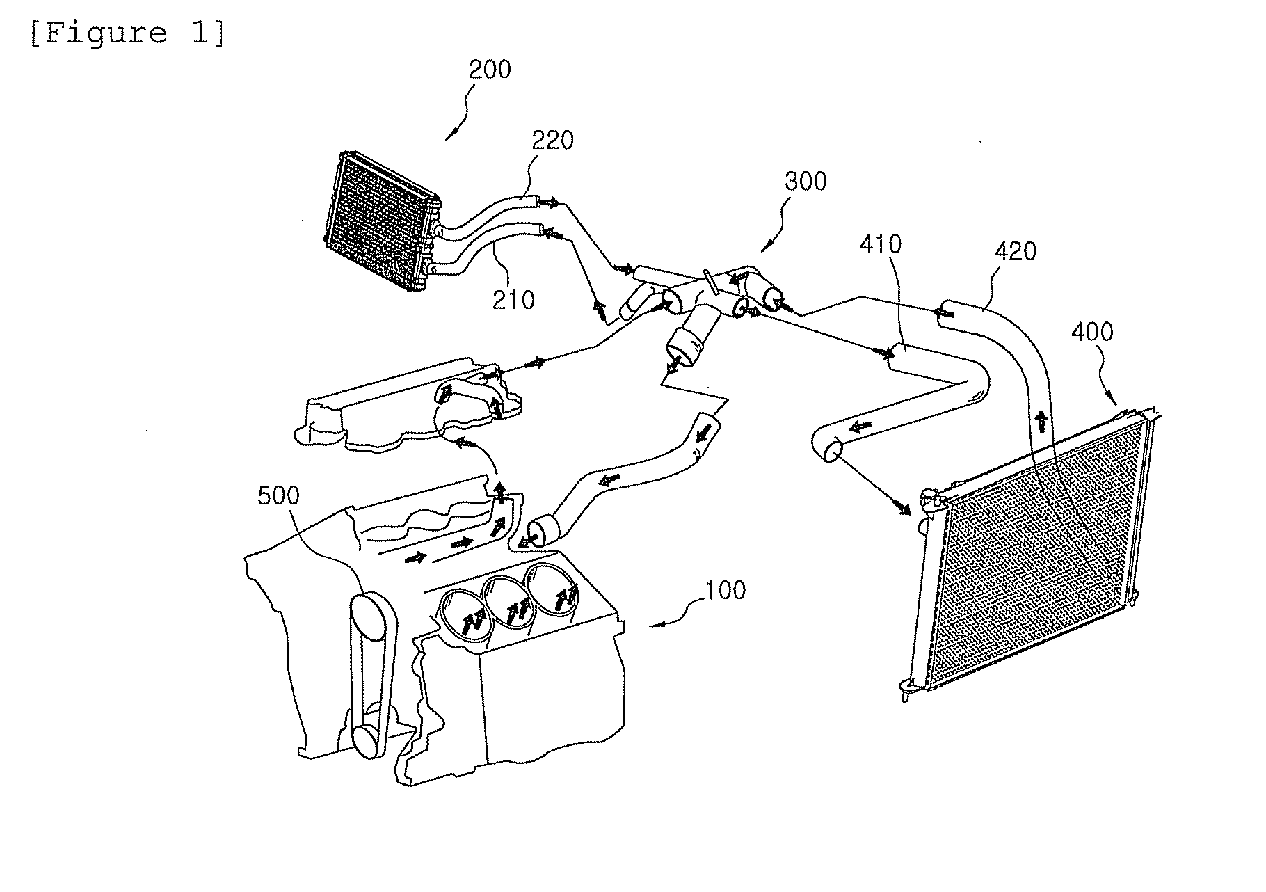
[0023]As shown in FIG. 1, a cooling system for a vehicle according to the present invention includes an engine 100 in which coolant is flowed along a passage formed in outer wall of a cylinder block, a heater core 400 through which high temperature coolant discharged from the engine 100 is flowed, a radiator 200, a thermostat 300 which controls flow direction of the coolant discharged from the engine 100 and a water pump 500 which receives power from a crank shaft (not shown) of the engine 100 to forcedly circulate the coolant.

[0024]In the cooling system for a vehicle, by an action of the water pump 500 operably connected to the crank shaft (not shown), the coolant heated at the engine 100 is cooled by exchanging heat with external air during it passes through the heater core 400 and the radiator 200 and then is flowed again into the engine 100 to perform the heat exchange with the high temperature engine 100.

[0025]Since the engine can maintain an appropriate temperature by the cool...


PUM


Abstract

Disclosed is a cooling system for a vehicle, in which coolant coolant, a blend of an antifreezing solution and water flowed into a radiator generates turbulent flow when a vehicle is in a state of a critical driving mode of a vehicle for example, a hill-climbing mode, thereby enhancing heat radiating performance and reducing pressure drop amount at the same time.

Description

CROSS REFERENCE TO RELATED APPLICATIONS[0001]This application is a continuation-in-part of U.S. patent application Ser. No. 11 / 640,605, filed on Dec. 18, 2006.TECHNICAL FIELD[0002]The present invention relates to a cooling system for a vehicle, in which a coolant, a blend of an antifreezing solution and water flowed into a radiator generates turbulent flow when a vehicle is in a state of a critical driving mode of a vehicle for example, a hill-climbing mode.BACKGROUND ART[0003]In U.S. Pat. No. 4,332,293 there is suggested a numerical range in that the length of a fin in a direction of air flow should be 12 to 23 mm, the pitch of the fin should be 1.5 to 3.3 mm, and the pitch of a tube should be 8.5 to 14 mm as elements of a radiator mounted within a range of a limited core mounting space so as to overcome air resistance generated as the length of the fin is lengthened in the direction of air flow in the radiator with a tube arrangement of 2 or 3 rows and reduction of heat transfer p...

Claims


Application Information

Patent Timeline
Patent Type & Authority Applications(United States)
IPC IPC(8): F01P7/14
CPCF01P7/164F28D2021/0094F28D1/05366F01P2003/001
Inventor SIM, HO CHANGJEONG, SUN ANJUN, GIL WOONGCHO, BYOUNG SUNLEE, SANG YULJUNG, KWANG YONG
Owner HALLA CLIMATE CONTROL
Learn More