Lubricant Dispenser

a technology of lubricant dispenser and lubricant dispenser, which is applied in the direction of lubricating pumps, engine components, immersion cells, etc., can solve the problems of increased diffusion loss, reduced lubrication efficiency, and reduced lubrication efficiency, so as to achieve good barrier effect and sufficient stability

Inactive Publication Date: 2009-02-12
PERMA TEC
View PDF4 Cites 21 Cited by
  • Summary
  • Abstract
  • Description
  • Claims
  • Application Information

AI Technical Summary

Benefits of technology

[0021]In a preferred production method, the housing mantle can also have multiple layers, which can be formed from different polymers. In order to achieve a particularly good barrier effect with the multi-component injection-molding method described above, both the barrier layer and the second component have an admixture of layer substances, and the weight proportion of the layer substances in the second component is lower than in the barrier layer, so that the second component still has sufficient stability.

Problems solved by technology

In the case of the known lubricant dispensers, there is the problem that the gas generated in the lubricant dispenser diffuses out of the housing, to a certain degree, and therefore can only be partially utilized to build up pressure in the pressure chamber and for dispensing lubricant.
The losses due to diffusion through the housing walls in the case of a long total lubrication duration of the lubricant dispenser, which can typically last up to a year and more, are particularly serious.
Accordingly, the diffusion losses also increase with continuing emptying.
Application of the metal layer is complicated, and a user can check the fill level only if the narrow, uncovered longitudinal region remains visible in the installed state.
If the metal layer is disposed on the inside of the container mantle, circumference-side sealing of the piston in the uneven transition region between the metal layer and the viewing window becomes difficult.
If the metal layer is disposed on the outside of the container, the barrier effect is unsatisfactory, since diffusion of the gas through the plastic material cannot be effectively prevented.
The production of the at least three layers is complicated.

Method used


Image

  • Lubricant Dispenser
  • Lubricant Dispenser
  • Lubricant Dispenser

Examples


Embodiment Construction

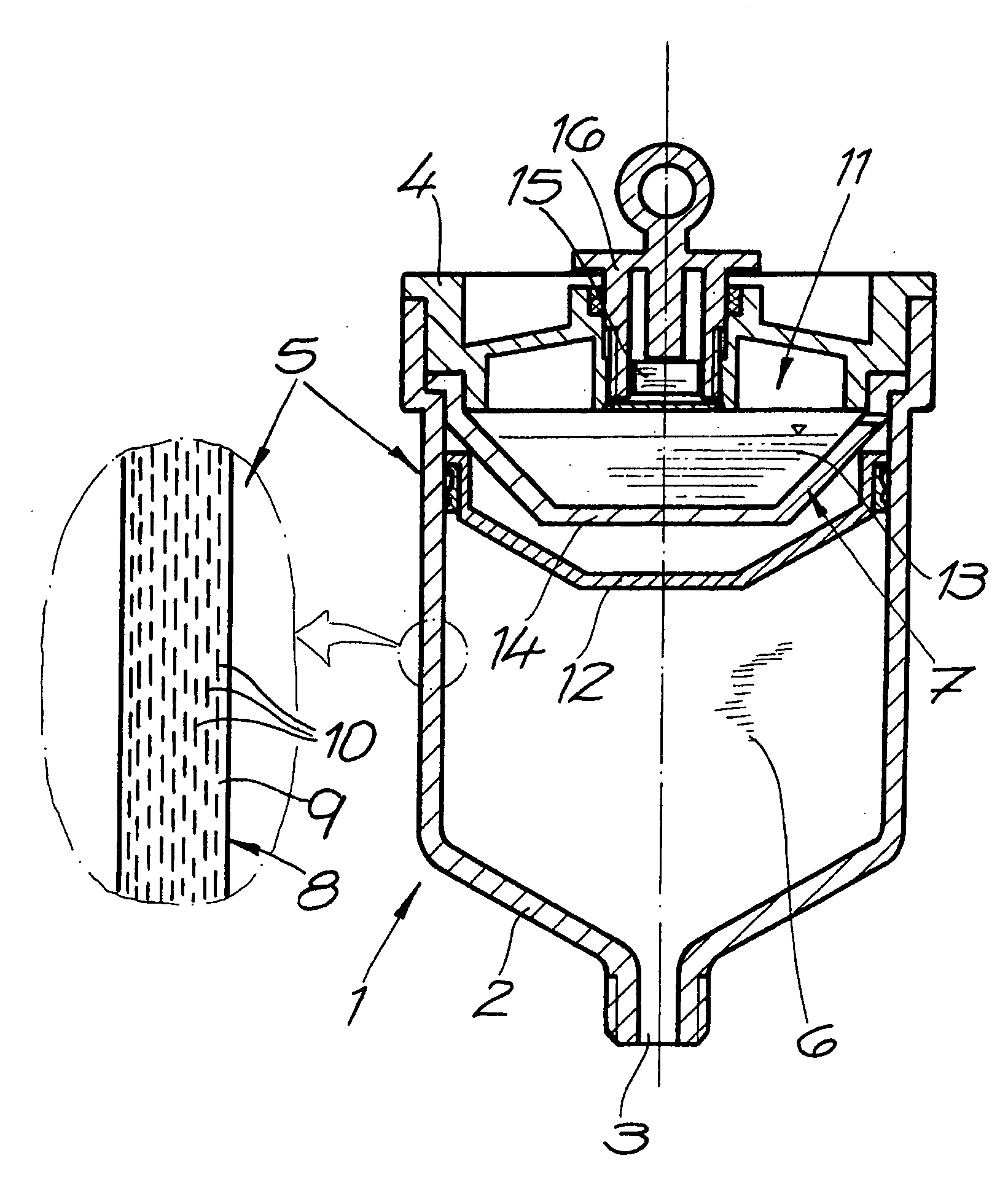
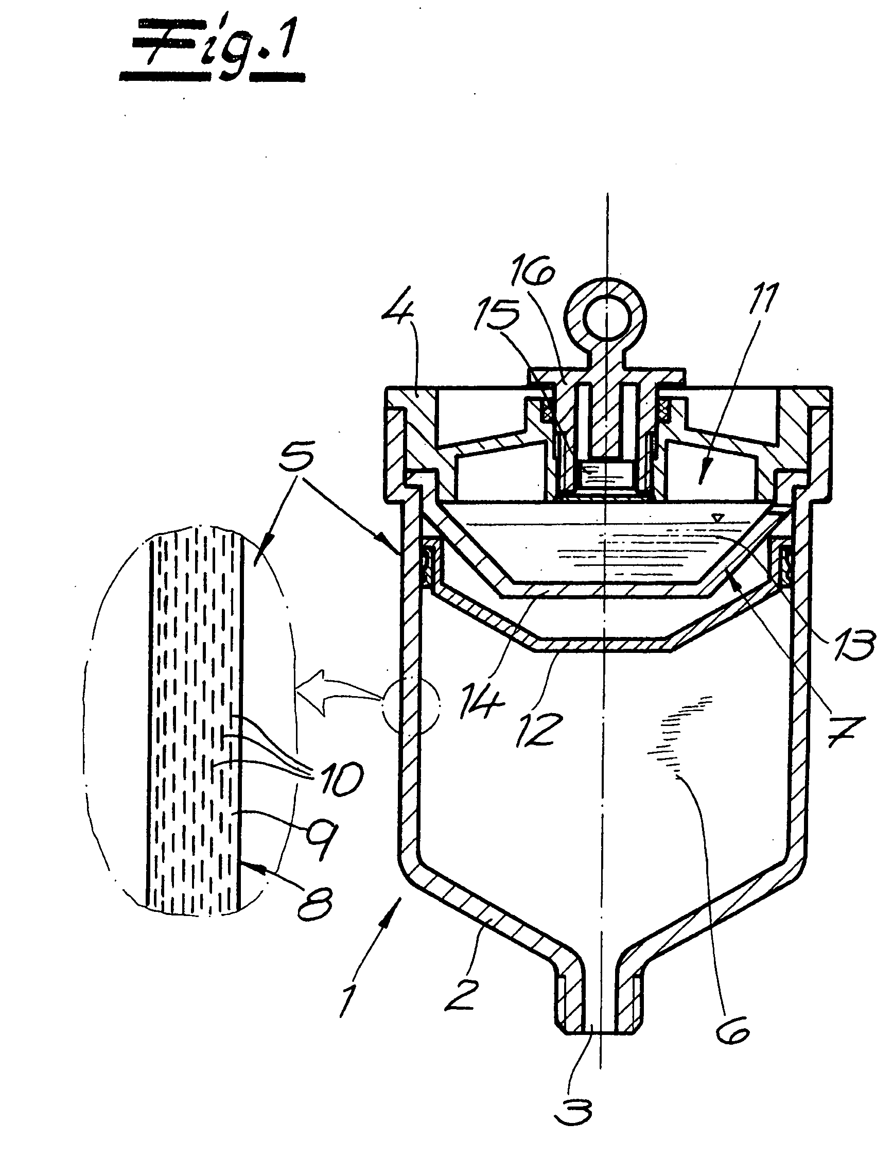
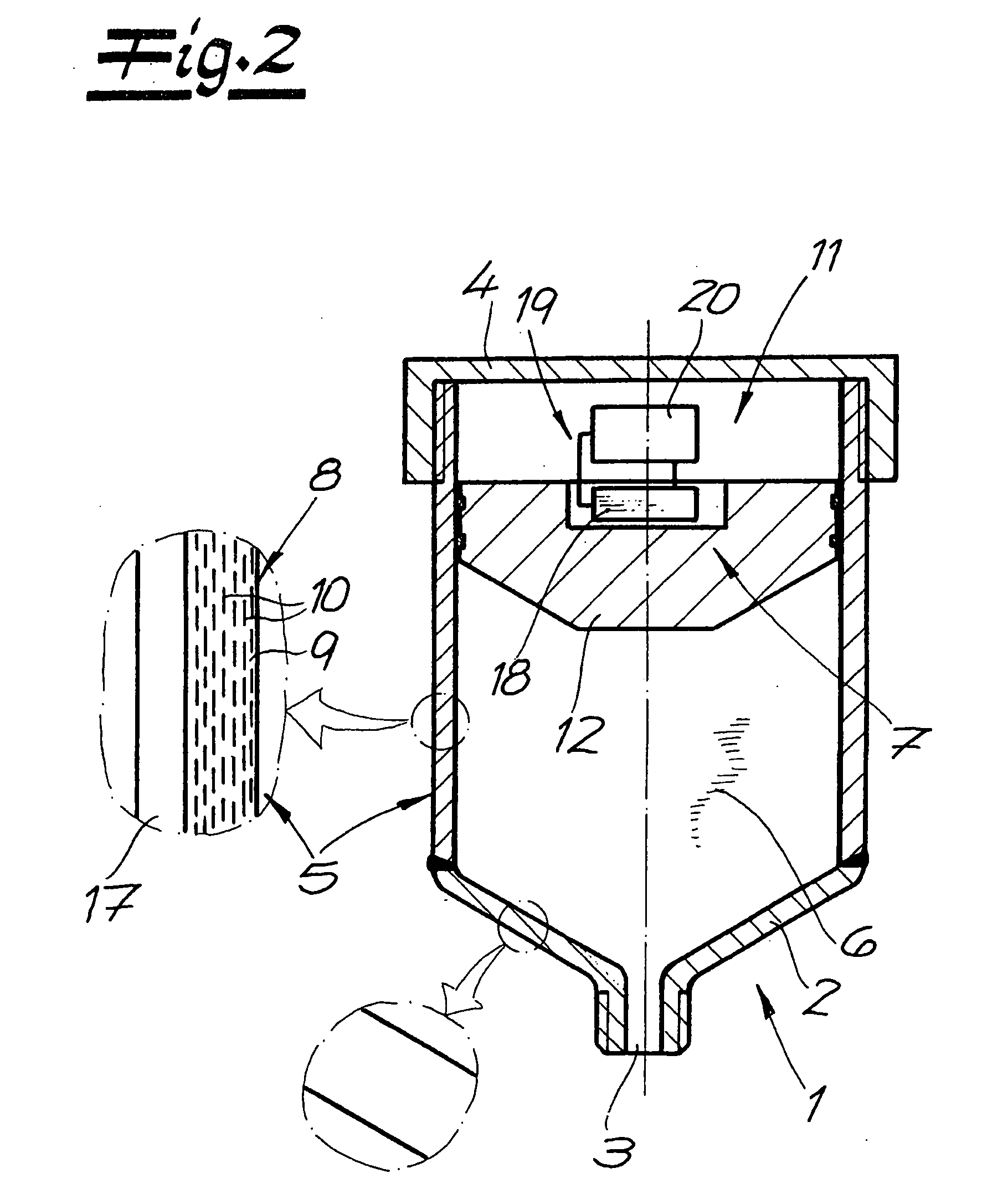
[0028]Referring now in detail to the drawings, the general structure of a lubricant dispenser according to the invention can be seen in FIGS. 1, 2, and 4. A housing 1 of the lubricant dispenser has a bottom 2 having a housing opening 3, a lid 4, and a cylindrical, preferably a circular cylindrical housing mantle 5 between them. A lubricant reservoir 6 that follows the housing opening 3 and a gas generator 7 for pressing the lubricant out through housing opening 3 are situated in housing 1. In the lubricant dispensers shown, housing mantle 5 is transparent or at least translucent, and has a barrier layer 8, at least in some sections, which has a polymer base substance 9 and an admixture of layer substances 10 to improve the barrier properties. A pressure chamber 11 for the gas formed by gas generator 7 is separated from lubricant reservoir 6 by a piston 12. Piston 12 is moved by the built-up pressure and the lubricant is pressed out through housing opening 3. The position of piston 1...


PUM


Abstract

A lubricant dispenser has a housing that has a bottom with a housing opening, a lid, and a housing mantle between them, a lubricant reservoir, and a gas generator disposed in the housing for pressing the lubricant out. The housing mantle is transparent or translucent, at least in some sections, and has at least one barrier layer. The barrier layer has a polymer base substance and an admixture of typically inorganic layer substances to improve the barrier properties.

Description

CROSS REFERENCE TO RELATED APPLICATIONS[0001]Applicant claims priority under 35 U.S.C. 119 of German Application No. 10 2007 037 422.6 filed Aug. 8, 2007.BACKGROUND OF THE INVENTION[0002]1. Field of the Invention[0003]The invention relates to a lubricant dispenser having a housing that has a bottom with a housing opening, a lid, and a housing mantle, a lubricant reservoir, and a gas generator disposed in the housing for pressing the lubricant out. The housing mantle is transparent or translucent, at least in some sections, and has at least one barrier layer. The housing mantle extends between the bottom and the lid of the housing, and usually has a cylindrical shape. The shape of the housing mantle is not restricted to the shape of a circular cylinder, but can also have any other desired footprint, for example an oval or angular shape. The bottom and / or the lid can be formed in one piece with the housing mantle, in one production step, or connected with it with a material fit. The b...

Claims


Application Information

Patent Timeline
Patent Type & Authority Applications(United States)
IPC IPC(8): F16N11/10
CPCH01M6/34F16N11/10
Inventor EISENBACHER, EGON
Owner PERMA TEC
Why Eureka
Try Eureka