Apparatus for Delivering Sealant at a Predetermined Pressure to a Stuffing Box of a Shaft

Active Publication Date: 2009-02-12
TAMAR R C TECH DEV
View PDF4 Cites 6 Cited by
  • Summary
  • Abstract
  • Description
  • Claims
  • Application Information

AI Technical Summary

Benefits of technology

[0030]In one aspect, vanes attached to an impeller disc front face are oriented and/or shaped such that the working fluid is deflected to the front face periphery whereby to increase the working fluid pressure acting on the impeller disc periphery, and vanes attached to the corresponding impeller disc rear face are oriented and/or shaped such that the working fluid flowing from the front to rear face is deflected to a rear face central portion whereby to increase the working fluid pressure acting on the impeller disc central portion, the working fluid pressure acting on the impeller disc rear face central portion being substantially equal to, and in an opposite direction in cou

Problems solved by technology

Such a seal is generally expensive and tends to rupture at once without any prior indication.
The repair of a faulty mechanical seal is costly and time consuming, necessitating extensive rotary machine downtime.
Although the rope packing slowly loosens and therefore provides early indication as to working fluid leakage, the packing material erodes relatively quickly due to frictional heat buildup and needs to be replaced often by the time consuming replacement procedure.
Labyrinth seals are suitable for high shaft speeds; however they require accurate positioning with respect to the shaft and are therefore relatively expensive.
Frictional forces acting on the shaft as it is rotated about the wall of the shaft opening result in erosion and diminishment of the sealant, and eventually the surface tension of the remaining sealant is not sufficient to prevent the leakage of the working f

Method used


Image

  • Apparatus for Delivering Sealant at a Predetermined Pressure to a Stuffing Box of a Shaft
  • Apparatus for Delivering Sealant at a Predetermined Pressure to a Stuffing Box of a Shaft
  • Apparatus for Delivering Sealant at a Predetermined Pressure to a Stuffing Box of a Shaft

Examples


Embodiment Construction

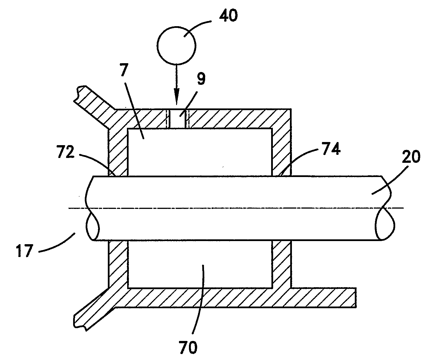
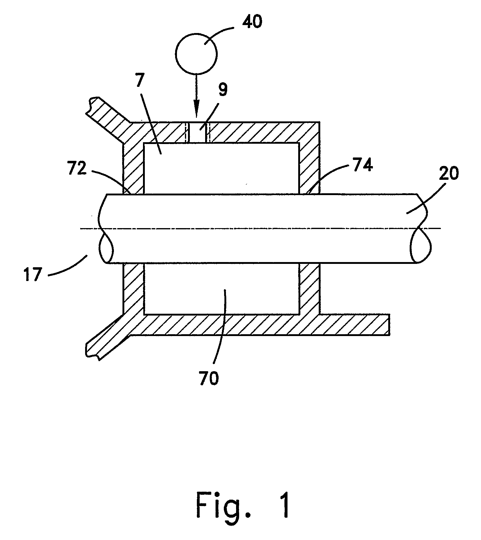
[0048]The present invention is a novel apparatus for delivering viscous sealant at a predetermined pressure to a stuffing box of a machine, e.g. a rotary machine such as a pump, compressor, and turbine, which produces work by means of a shaft and a working fluid circulating within a working chamber. The apparatus comprises a sealant delivery unit which automatically delivers sealant by means of a constant external force when the sealant pressure within a stuffing box in proximity to the working chamber is lowered, indicating sealant erosion. The sealant pressure within the stuffing box is sufficient to promote the adhesion of sealant to the shaft.

[0049]The following description relates to the adhesion of sealant to a rotary shaft, but it will be appreciated that the invention can be similarly implemented to facilitate the adhesion of sealant to a linearly displaceable shaft.

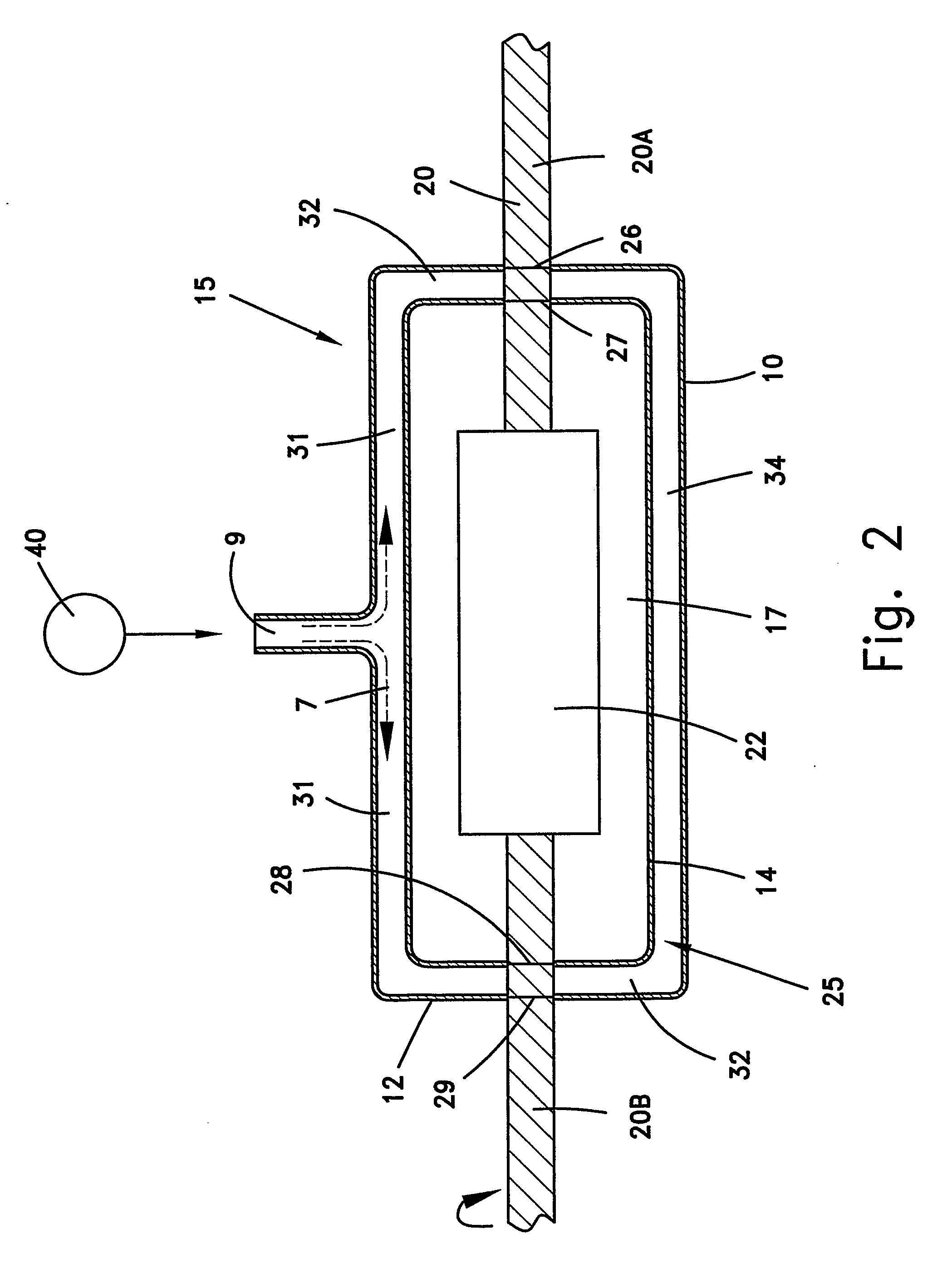
[0050]FIG. 1 illustrates a vertical cross section of one configuration of a stuffing box 70 which is adjacent ...


PUM

PropertyMeasurementUnit
Pressureaaaaaaaaaa

Abstract

A delivery unit (40) for automatically delivering a viscous sealant at a predetermined pressure to a stuffing box (70)of a shaft (20) is disclosed. The delivery unit (40), such as a pressure booster incrementally displaceable piston, is controlled to deliver the sealant at a predetermined pressure on demand when the pressure of the sealant within said stuffing box is less than the predetermined delivery pressure being sufficient to promote adhesion of the sealant onto a shaft segment and to thereby prevent or retard the egress of working fluid from a corresponding working chamber (17) of a machine adapte to perform work by the shaft. A system for reducing the pressure of sealant within a stuffing box by use of the delivery unit and of an impeller-based dynamic seal is also disclosed.

Description

FIELD OF THE INVENTION[0001]The present invention relates to the field of sealants. More particularly, the invention relates to an apparatus for automatically delivering a sealant at a predetermined pressure to a stuffing box of a shaft.BACKGROUND OF THE INVENTION[0002]Many types of heavy rotary machinery, including pumps, compressors, and turbines, (hereinafter a “rotary machine”) produce work by means of a working fluid enclosed within a working chamber as its main shaft is rotated. Although the clearance between the shaft and the rotary machine housing is relatively small, the working fluid tends to leak from each housing opening through which the shaft extends (hereinafter referred to as a “shaft opening” for brevity). A seal is generally used in the proximity of a shaft opening, to prevent the leakage of working fluid therefrom.[0003]Numerous seal types are known. For low speed rotary machines, a known seal type is a spring loaded gasket, such as an O-ring. For high speed rotar...

Claims


Application Information

Patent Timeline
IPC IPC(8): B67D5/00F04D29/10B65D83/00B67D5/08B67D5/22B67D99/00B67D7/08B67D7/22
CPCF16J15/406F16J15/181
Inventor COHEN-ZADA, VAITZMAN
Owner TAMAR R C TECH DEV
Why Eureka
Try Eureka