Active shield superconducting electromagnet apparatus and magnetic resonance imaging system

a superconducting electromagnet and magnetic resonance imaging technology, applied in superconducting magnets/coils, instruments, magnetic bodies, etc., can solve the problem of affecting the magnetic field in the imaging region of the mri system, changelessness in the total amount of magnetic field, and the inability to generate such a supercurrent as to cancel the electromotive, etc., to achieve the effect of suppressing a large current flow

Inactive Publication Date: 2009-02-12
HITACHI LTD
View PDF10 Cites 11 Cited by
  • Summary
  • Abstract
  • Description
  • Claims
  • Application Information

AI Technical Summary

Benefits of technology

[0011]An aspect of the present invention provides an active shield superconducting electromagnet apparatus and a magnetic resonance imaging system which suppress a large current flow through a superconducting fault current limiter even if a main coil or a shield coil is quenched.

Problems solved by technology

In the MRI system using the superconducting electromagnet apparatus, it is well known that variation in the outer magnetic field environment, caused by passage or stop of a vehicle in the vicinity, or up and down of an elevator, etc., can affect the magnetic field in the imaging region of the MRI system to interfere with imaging.
However, considering the superconducting coil itself, even if variation occurs in a total amount of the magnetic field surrounded by that superconducting coil, an electromotive force should be generated to compensate for a supercurrent to keep the total amount of the magnetic field, and should result in changelessness in the total amount of the magnetic field.
However, since a reverse electromotive force is generated in the main coil and the shield coil when the disturbance magnetic field crosses the main coil and the shield coil connected in series, it is impossible to generate such a supercurrent as to cancel the electromotive force in the main coil and the shield coil to suppress the disturbance magnetic field.
However, it is not easy to make a superconducting fault current limiter which has a larger resistance than ever before in a normal conducting state, and functions as a superconducting wire in normal operation.

Method used


Image

  • Active shield superconducting electromagnet apparatus and magnetic resonance imaging system
  • Active shield superconducting electromagnet apparatus and magnetic resonance imaging system
  • Active shield superconducting electromagnet apparatus and magnetic resonance imaging system

Examples


first embodiment

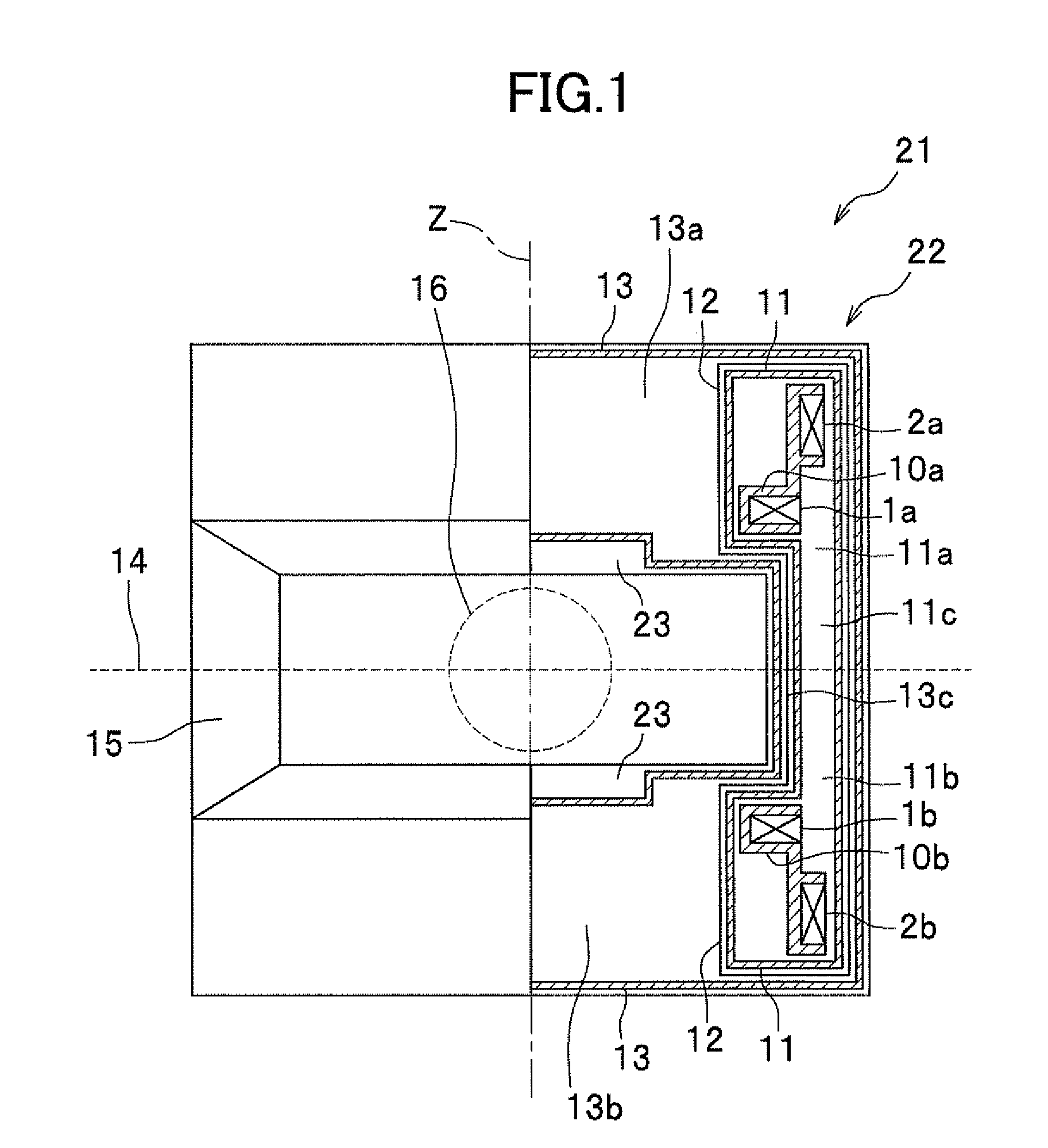
[0026]FIG. 1 shows a left side view of a nuclear magnetic resonance imaging (MRI) apparatus according to the first embodiment of the present invention on the left, and shows a right sectional view of the MRI system on the right. As shown in FIG. 1, the MRI system 21 of open-type is exemplified. The open-type MRI system includes an active shield superconducting electromagnet apparatus 22 and an inspection apparatus arrangement region 23.

[0027]The superconducting electromagnet apparatus 22 includes a pair of main coils 1a and 1b and a pair of shield coils 2a and 2b. Each of the pair of main coils 1a and 1b is symmetrically arranged with an equatorial plane 14 as a symmetric plane, and each central axis of those coincides with each other. To coincide with these central axes, a Z-axis, which is perpendicular to the equatorial plane 14, may be provided. The main coils 1a and 1b can generate a main magnetic field in the same Z-axis direction as that of the homogeneous magnetic field gener...

second embodiment

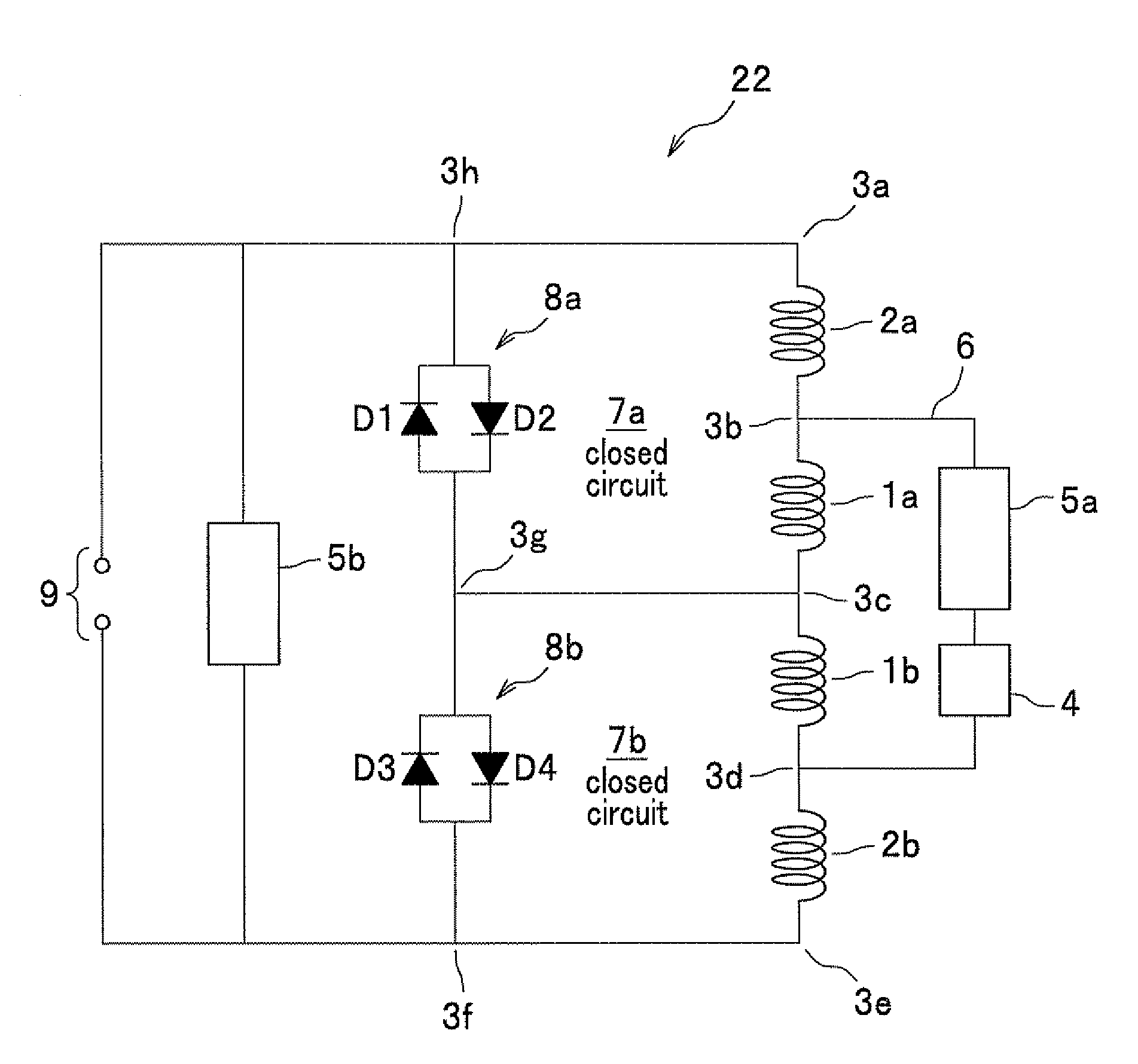
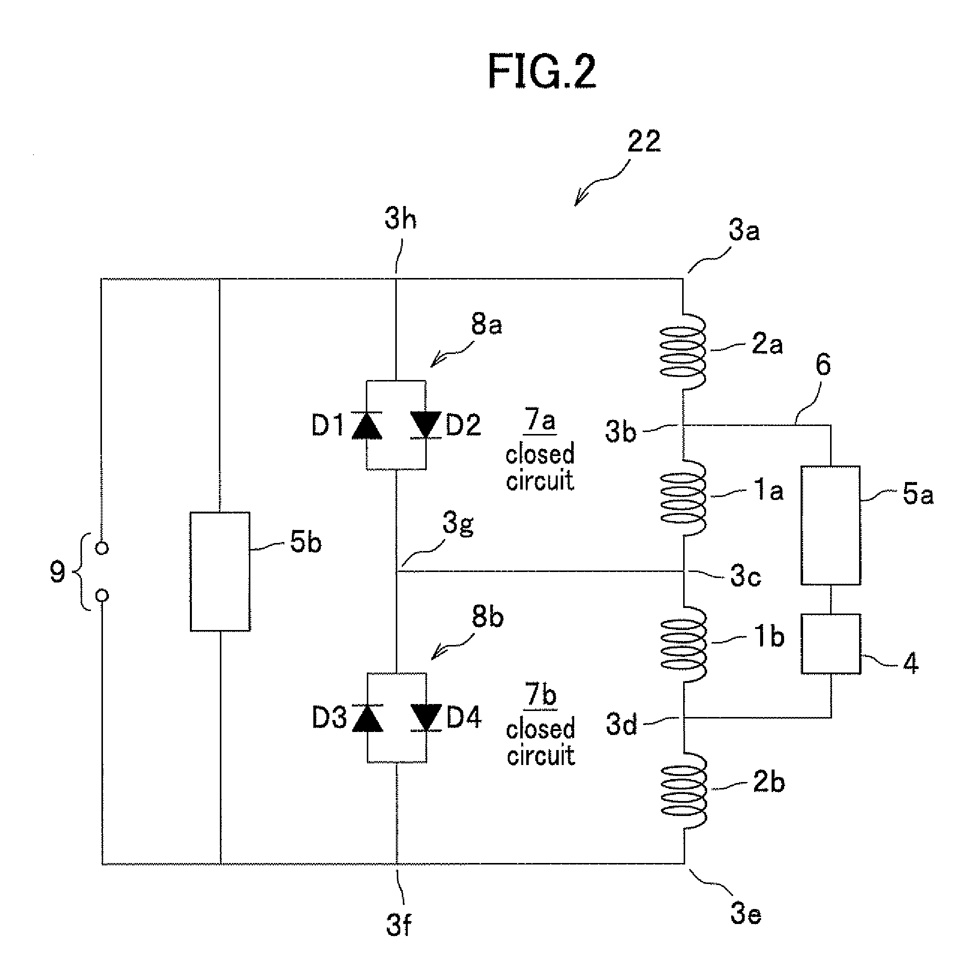
[0050]FIG. 4 is a schematic circuit diagram of the active shield superconducting electromagnet apparatus 22 according to a second embodiment of the present invention. As shown in FIG. 4, the superconducting electromagnet apparatus 22 according to the second embodiment of the present invention differs from the superconducting electromagnet apparatus 22 of the first embodiment in that the first main coil 1a, the second main coil 1b, the first shield coil 2a, and the second shield coil 2b are connected in series in order of the first shield coil 2a, the second main coil 1b, the first main coil 1a, and the second shield coil 2b. Further, like the first embodiment, coils are arranged on the Z-axis in order of the first shield coil 2a, the first main coil 1a, the second main coil 1b, and the second shield coil 2b from up to down as shown in FIG. 1.

[0051]By this difference, the first closed circuit 7a is made up to include the second main coil 1b instead of the first main coil 1a. Also, th...

third embodiment

[0056]FIG. 5 is a schematic circuit diagram of the active shield superconducting electromagnet apparatus 22 according to a third embodiment of the present invention. As shown in FIG. 5, the superconducting electromagnet apparatus 22 according to the third embodiment of the present invention differs from the superconducting electromagnet apparatus 22 of the first embodiment in that quench protection circuits 8a-8d are individually provided for the first shield coil 2a, the first main coil 1a, the second main coil 1b, and the second shield coil 2b.

[0057]By connecting the first shield coil 2a, and a first quench protection circuit 8a, through which a current does not flow in the absence of potential difference between both ends of which, and through which a current flows in the presence of potential difference between both ends of which, in series, the first closed circuit 7a is made up. More concretely, the first closed circuit 7a is made up by connecting the first shield coil 2a-nod...


PUM


Abstract

The active shield superconducting electromagnet apparatus includes: a main switching circuit in which first and second main coils, first and second shield coils, and a first superconducting persistent current switch are connected in series; a sub switching circuit in which a bypass circuit, in which a superconducting fault current limiter and a second superconducting persistent current switch are connected in series, are connected to a series circuit of the first main coil and the second main coil in parallel; a first closed circuit in which at least one of the first main coil and the first shield coil, and a first quench protection circuit are connected in series; and a second closed circuit in which one of the second main coil and the second shield coil, and a second quench protection circuit are connected in series.

Description

CROSS REFERENCE TO RELATED APPLICATIONS[0001]The present application claims benefit of the filing date of JP 2007-204909 A filed on Aug. 7, 2007 which is incorporated herein by reference.FIELD OF THE INVENTION[0002]The present invention relates to an active shield superconducting electromagnet apparatus and a magnetic resonance imaging (hereinafter, referred to as MRI) system using the same.DESCRIPTION OF THE RELATED ART[0003]The MRI system can image a living body tissue by utilizing the fact that the nuclear magnetic resonance (hereinafter, referred to as NMR) phenomena of hydrogen nuclei of hydrogen atoms in the living body are different in each tissue of the living body, and can visualize a magnitude of the resonance, or a quickness of temporal change in the resonance, both of which are different for each tissue, as a contrast at every position in the image.[0004]The MRI system measures an electromagnetic wave emitted by hydrogen nuclear spin by the NMR phenomenon, processes the ...

Claims


Application Information

Patent Timeline
Patent Type & Authority Applications(United States)
IPC IPC(8): H02H7/00
CPCG01R33/288G01R33/3806H01F6/02G01R33/421G01R33/3815
Inventor HIGUCHI, YOSHIYAABE, MITSUSHIANDO, RYUYAYAMAMOTO, TSUTOMUHONDA, TAKURO
Owner HITACHI LTD
Why Eureka
Try Eureka