
Electrode for Alkali Fuel Cell and Method for Making a Fuel Cell Including at Least One Step of Making Such an Electrode

a fuel cell and electrode technology, applied in the manufacture of cell components, final product manufacturing, electrochemical generators, etc., can solve the problems of inability to achieve optimal efficiency of electrodes comprising such active layers, inability to achieve active layer preparation techniques that are not suitable for industrial manufacturing, and inability to achieve active layer preparation techniques. to achieve the effect of easy implementation

Inactive Publication Date: 2009-02-12
COMMISSARIAT A LENERGIE ATOMIQUE ET AUX ENERGIES ALTERNATIVES +2
View PDF8 Cites 21 Cited by
  • Summary
  • Abstract
  • Description
  • Claims
  • Application Information

AI Technical Summary

Benefits of technology

The invention provides an electrode for alkali fuel cells that has optimal efficiency and is easy to implement. The electrode has a unique structure consisting of a catalytic layer and a porous layer, which allows for improved electronic conduction, hydroxide ion conduction, and catalytic properties. The method for manufacturing the electrode is simple and suitable for industrial production. The technical effects of the invention are improved performance and ease of implementation of the electrode for alkali fuel cells.

Problems solved by technology

The efficiency of an electrode comprising such an active layer is not however optimal and the active layer is not easy to implement.
The active layer preparation techniques are not in fact suitable for industrial manufacturing.
The particular distribution of the particles within the polymer matrix and the composite material obtained do not however enable an active electrode layer ensuring optimal operation of an alkali fuel cell to be obtained.
Although it has satisfactory catalytic properties, the active electrode layer does not in fact contain any hydroxide ion conducting elements and the electronic conduction properties are limited.
The active layer thus formed can not however ensure optimal operation of alkali fuel cells.

Method used


Image

  • Electrode for Alkali Fuel Cell and Method for Making a Fuel Cell Including at Least One Step of Making Such an Electrode
  • Electrode for Alkali Fuel Cell and Method for Making a Fuel Cell Including at Least One Step of Making Such an Electrode

Examples


Embodiment Construction

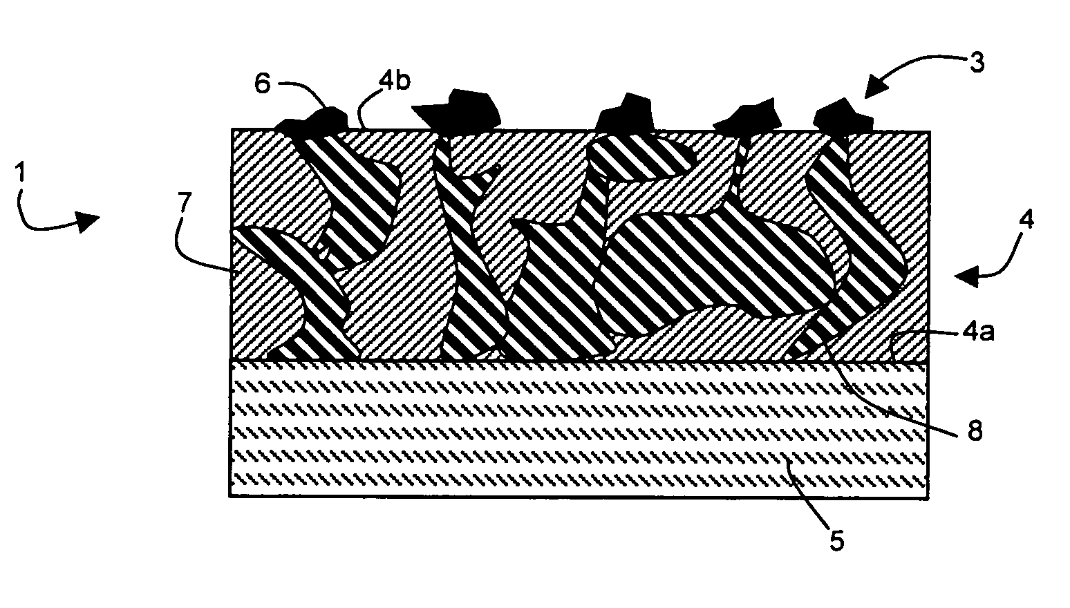
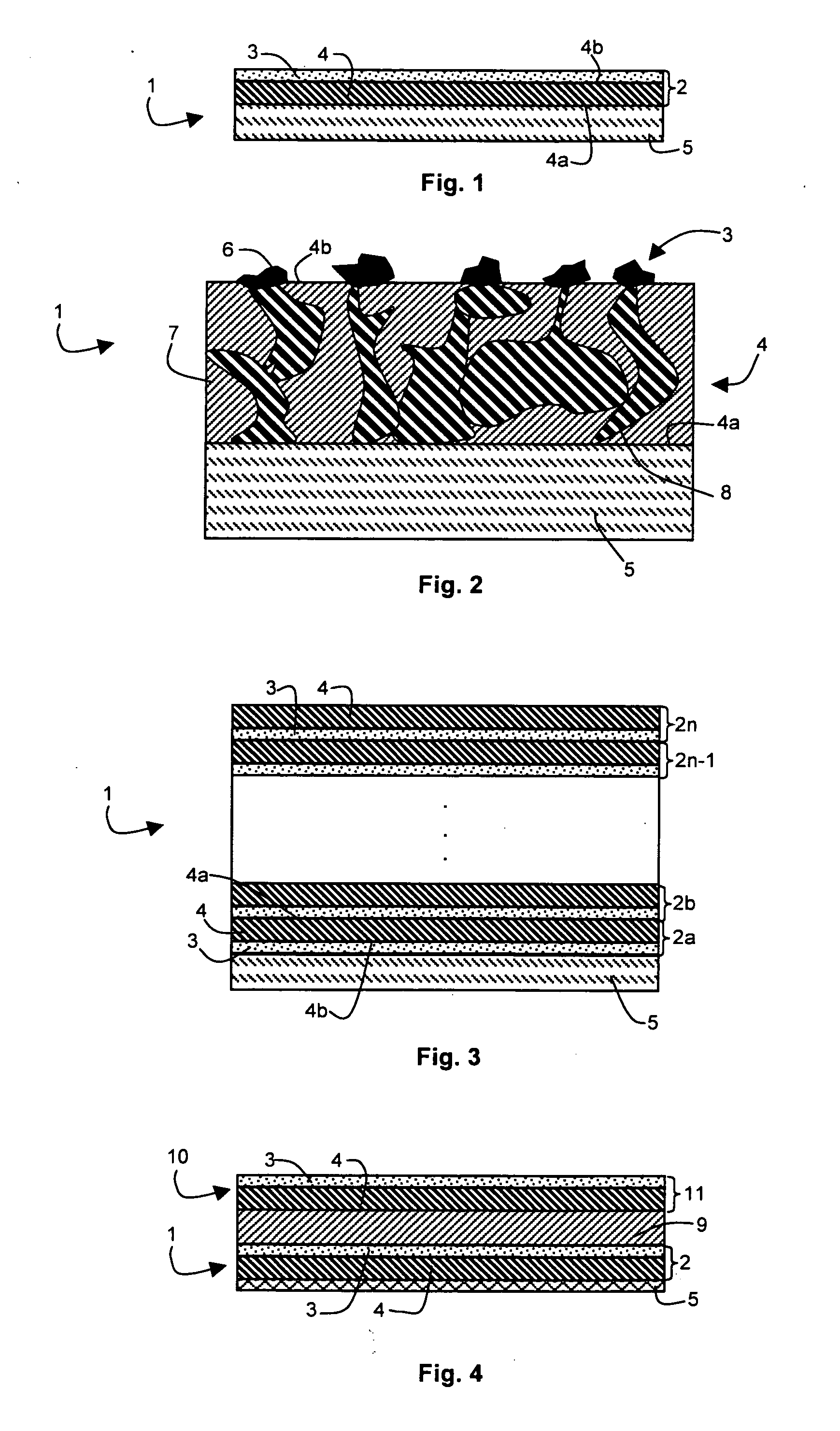
[0019]As represented in FIGS. 1 to 3, an electrode 1 for an alkali fuel cell comprises an active layer conducting electrons and hydroxide ions and being catalytic for an electrochemical reaction or reactions to take place in the alkali fuel cell.

[0020]The active layer is formed by a bilayer 2, i.e. by a thin film made up of two distinct superposed layers, or by a stack of a plurality of bilayers 2a, . . . , 2n, i.e. by a stack formed by an alternation of two distinct superposed thin layers. Each bilayer 2, 2a, . . . , 2n is therefore composed of a catalytic layer 3 and a porous layer 4 comprising two opposite faces 4a and 4b one of which is in contact with the catalytic layer 3.

[0021]Furthermore, the active layer can be arranged on an additional layer 5 that is preferably porous and electronically conducting. In this case, the first layer arranged on additional layer 5 can be either a porous layer 4 or a catalytic layer 3. Thus, in FIGS. 1 and 2, porous layer 4 of bilayer 2 is in co...


PUM

PropertyMeasurementUnit
thicknessaaaaaaaaaa
thicknessaaaaaaaaaa
thicknessaaaaaaaaaa

Abstract

An electrode for an alkali fuel cell comprises an active layer formed by a bilayer or by a stack of a plurality of bilayers. Each bilayer is composed of a catalytic layer comprising catalyst particles of nanometric size and of a porous layer comprising two opposite faces one of which is in contact with the catalytic layer. The porous layer is made from a porous composite material comprising a hydroxide ion conducting polymer matrix in which a metallic lattice is formed constituting a plurality of electronically conducting paths connecting the two opposite faces of the porous layer. Advantageously, fabrication of such an electrode is obtained by successively performing vacuum deposition of the catalyst particles and vacuum co-deposition of the hydroxide ion conducting polymer and of the metal on a free surface of a support.

Description

BACKGROUND OF THE INVENTION[0001]The invention relates to an electrode for an alkali fuel cell comprising at least an active layer that is an electronic conductor, conducting hydroxide ions, and catalytic.[0002]The invention also relates to a method for making an alkali fuel cell including at least one step of making such an electrode.STATE OF THE ART[0003]Known Alkali Fuel Cells, also referred to as AFC, are generally formed by two electrodes and a liquid or solid electrolyte exchanging or conducting hydroxide ions OH−.[0004]Patent Application WO-A-2005 / 069413 describes for example an alkali fuel cell comprising a solid stack formed by a first electrode, a solid conducting hydroxide ions membrane and a second electrode. Each electrode of the stack comprises at least an active layer in contact with the solid membrane. Each active layer presents electronic conduction properties, hydroxide ion conduction properties and catalytic properties for the electrochemical reaction or reactions...

Claims


Application Information

Patent Timeline
Patent Type & Authority Applications(United States)
IPC IPC(8): H01M8/10H01M4/88H01M4/86
CPCH01M4/8605H01M4/8673H01M4/8803H01M4/8853H01M4/886Y10T29/49115H01M4/92H01M4/921H01M8/083H01M2004/021Y02E60/50H01M4/8867Y02P70/50Y02E60/10
Inventor MARTINENT, AUDREYLAURENT, JEAN-YVESPERRIN, MAXSCHIEDA, MAURICIODURAND, JEANROUALDES, STEPHANIE
Owner COMMISSARIAT A LENERGIE ATOMIQUE ET AUX ENERGIES ALTERNATIVES
Learn More