
Automatic Solar Compass

a solar compass and solar energy technology, applied in the field of automatic solar compass, can solve the problems of complex operation of solar compass, gps signal does not contain direction information, and requires elaborate manual adjustments

Inactive Publication Date: 2009-02-19
THE TRUSTEES OF COLUMBIA UNIV IN THE CITY OF NEW YORK
View PDF13 Cites 18 Cited by
  • Summary
  • Abstract
  • Description
  • Claims
  • Application Information

AI Technical Summary

Benefits of technology

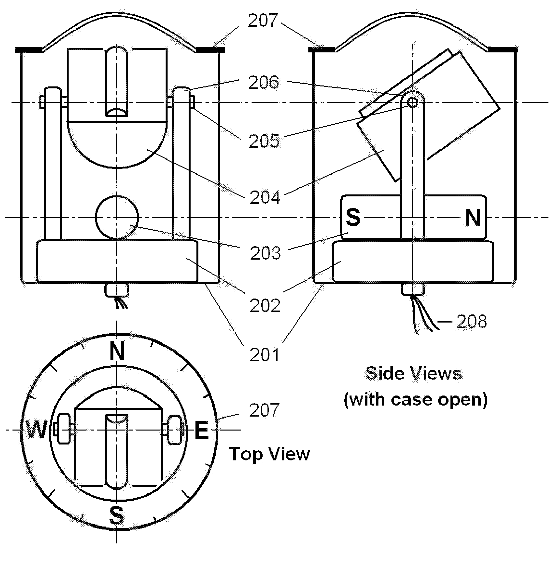
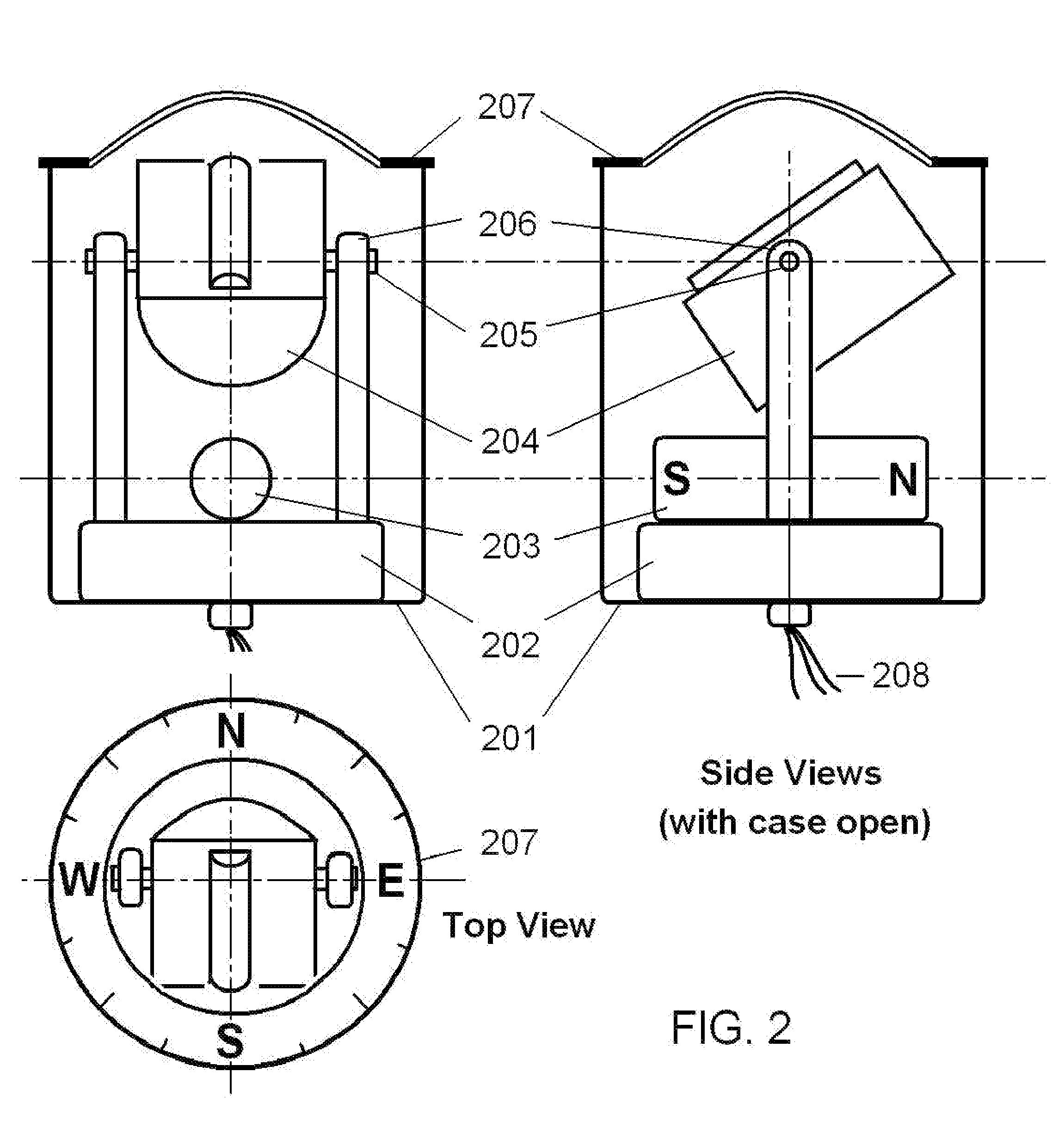
[0008]The current invention uses a cylindrical omni-directional lens to project the sunlight to a sharp and narrow line of light on an array of photo-detectors arranged on a semicircular base. The cylindrical omni-directional lens and the photo-detector array are contained in a light-tight case to become a detector assembly. If the axis of the detector assembly is aligned perfectly to the true south (or equivalently, true north), the location of the focused sunlight on the photo-detector array can be predicted accurately based on the date of the year, the local time, the latitude and longitude of the location, and the astronomical data. If there is a deviation between the detected location and the predicted location, the deviation is sent to a servomechanism, and a torque is generated to rotate the detector assembly to align it with the true south (or equivalently, true north). Once the deviation is eliminated, the axis is aligned to the true south (and equivalently the true north), the detection assembly becomes stationary, and then the true north is found.
[0010]Therefore, the operation of the said automatic solar compass is as easy as a magnetic compass. If the power is turned off or there is no sunlight, it functions as a magnetic compass. When the power is turned on and there is sunlight, the compass automatically points to the true north if it is different from the magnetic north.

Problems solved by technology

However, the operation of those solar compasses is very complicated, which requires the calculation of the local solar time versus the local standard time at the time of measurement, and requires elaborate manual adjustments.
However, the GPS signal does not contain direction information.
Although very accurate, its application is complicated and time-consuming.

Method used


Image

  • Automatic Solar Compass
  • Automatic Solar Compass
  • Automatic Solar Compass

Examples


Embodiment Construction

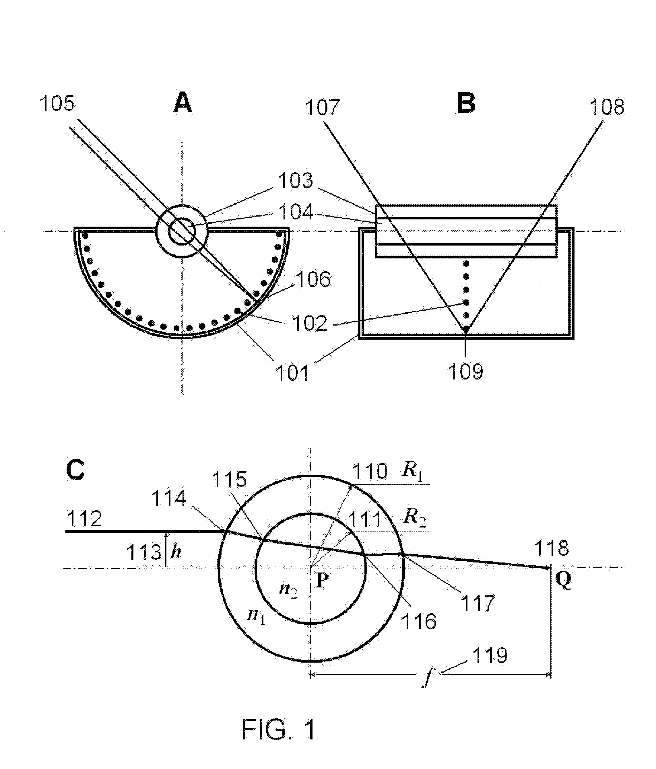
[0016]FIG. 1A and B show two cross sections of the detector assembly. It has an opaque and light-tight case 101. An array of photo-detectors 102 is placed at the middle of the case, to form a semi-circle. On the top side of the detector assembly is a cylindrical omni-directional lens, comprises of an outer cylinder 103 and an inner (solid) cylinder 104. The parallel light beams 105 of the sunlight converge at a point 106 on one of the photo-detectors placed on the inner wall of the semi-cylindrical case 101. The length of the cylindrical lens is sufficiently large that the sunlight over more than 47° angle span, 107 to 108, can be projected onto the photo-detector array 102.

[0017]The principle of the cylindrical omni-directional lens is shown in FIG. 1C. It comprises two concentric cylindrical components. The outer cylinder 110 with radius R1 is made of a transparent material with index of refraction n1. The inner cylinder 111 with radius R2 is made of another transparent material o...


PUM


Abstract

The most accurate method of finding the true north is through astronomical observations, for example, by observing the position of the sun. However, the procedure is complicated. The instantaneous position of the sun must be calculated from astronomical data for each instance of observation, and the operator must wait for the predetermined time to come. Elaborate manual adjustments are required. The present invention discloses an automatic solar compass comprising a cylindrical omni-directional lens, a detection means, and a servomechanism. It is as easy to use as the magnetic compass, but much more accurate and reliable than the magnetic compass.

Description

BACKGROUND OF THE INVENTION[0001]1. Field of the Invention[0002]Finding the direction with regard to the true north is a necessity in everyday life, for example, in traveling, camping, sightseeing, driving, sailing, flying, exploration, land surveying, military activities, and the utilization of solar energy. Since the invention in the 11th century, the magnetic compass has been the most popular instrument for finding directions. It is well-known that the magnetic compass has a number of problems. The magnetic north is often grossly different from the true north. In the United States, the error (magnetic inclination) could be greater than ±20°, which also varies with location and time. In Canada, the error could be greater than ±45°. Furthermore, the magnetic compass is grossly affected by ferromagnetic materials in the neighborhood of the compass, for example, iron ore or steel pieces, such as vehicles and firearms.[0003]The current invention discloses a novel compass which can aut...

Claims


Application Information

Patent Timeline
IPC IPC(8): G01C17/34G02B3/00
CPCG02B3/06G01C17/34
Inventor CHEN, CHENGJUN JULIAN
Owner THE TRUSTEES OF COLUMBIA UNIV IN THE CITY OF NEW YORK
Learn More