
Piston with a skirt having oil flow slots

a technology of oil flow slots and pistons, which is applied in the direction of trunk pistons, machines/engines, plungers, etc., can solve the problems of internal combustion engines, undesirable exhaust emissions, and consumption of piston surfaces, so as to improve the guidance of the piston, reduce dynamic viscosity friction, and improve the oil flow

Active Publication Date: 2009-02-19
TENNECO
View PDF20 Cites 7 Cited by
  • Summary
  • Abstract
  • Description
  • Claims
  • Application Information

AI Technical Summary

Benefits of technology

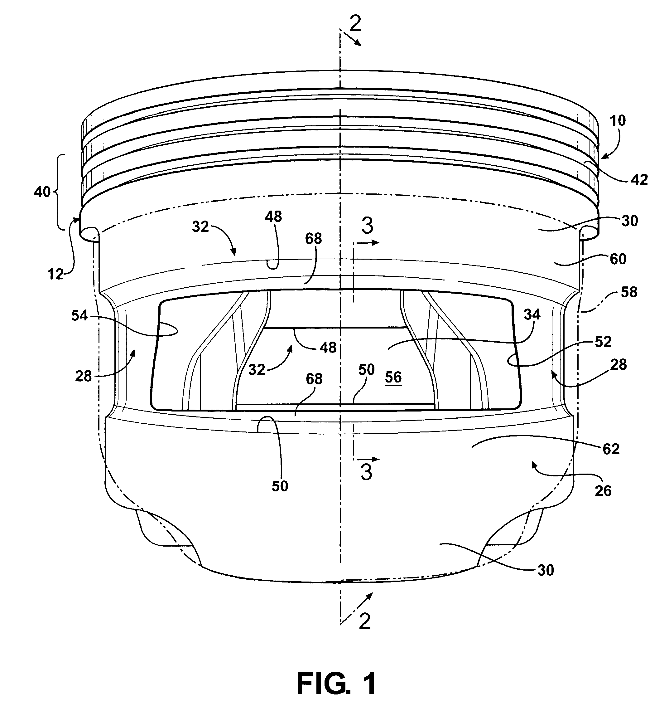
[0008]A piston for an internal combustion engine constructed according to one aspect of the invention has an upper crown portion with a pair of pin bosses depending therefrom and being joined as one piece with a pair of laterally spaced skirt portions. The skirt portions each have a slot extending therethrough to provide fluid communication between an outer surface of the skirt portions and an inner cavity partially bounded by the skirt portions. The slots have upper and lower edges extending generally transverse to the direction of piston reciprocation and sides extending between the upper and lower edges. The upper and lower edges have a contoured, proprietary shape to promote laminar and generally uniform oil flow and distribution over an outer surface of the piston over a cycle of the piston. The contoured shaped shape thereby directs at least some oil flow into the cavity of the piston, while also maintaining a desired hydrodynamic oil film external to the piston.
[0014]Pistons manufactured in accordance with the present invention improve oil flow over a complete cycle of the piston, reduce dynamic viscous friction over the cycle of the piston, improve the guidance of the piston throughout its complete cycle, reduce cylinder liner cavitation, reduce piston viscous friction loss, reduce carbon build-up in ring grooves of the piston and on piston rings with the grooves, improve the movement of the piston rings, reduce oil consumption and formed carbon adhered to the top land, therefore reducing bore polishing typically caused by carbon build-up, reduce exhaust emissions, and overall improve the running performance and life of the engine. The sum of these beneficial effects reduces engine fuel consumption and promotes more miles-to-gallon.

Problems solved by technology

It is known that internal combustion engines, and particularly diesel engines, experience high oil consumption that leads to undesirable exhaust emissions.
In addition, with the oil consumption comes carbon build-up on surfaces of pistons, particularly in the top land area, including in the annular ring grooves.
As such, the ring movements can be restricted by the carbon build-up, thereby diminishing the effectiveness of the rings to properly seal the combustion gas and control oil consumption, thereby resulting in increased oil blow-by, reduced engine performance, reduced engine component life, and increased emissions.
In addition to the problems mentioned above, an additional known problem can result from a non-uniform, turbulent flow of oil within the cylinder over the path of piston reciprocation.
Some of these additional problems include the onset of liner cavitation and increased friction between the piston and the cylinder liner.
Oil control loss can be traced to the high velocity of piston travel, generating a standing wave of oil.
If such is the case in the upper portion of the skirt, it results in a phenomenon referred to as “oil flooding”.
In some cases, such as when the gas pressure gradient across the ring belt is not clearly defined, the first ring groove floods, whereupon the oil consumption control characteristic is lost.
Exposure of this oil to the flame front decomposes and carbonizes the oil in the standing wave, generating soot and formation of carbon deposits.
As such, although it is desirable to maintain a continual supply of oil in the ring area of a piston, too much can be detrimental to the life of the engine and can also reduce the engine performance.

Method used


Image

  • Piston with a skirt having oil flow slots
  • Piston with a skirt having oil flow slots
  • Piston with a skirt having oil flow slots

Examples


Embodiment Construction

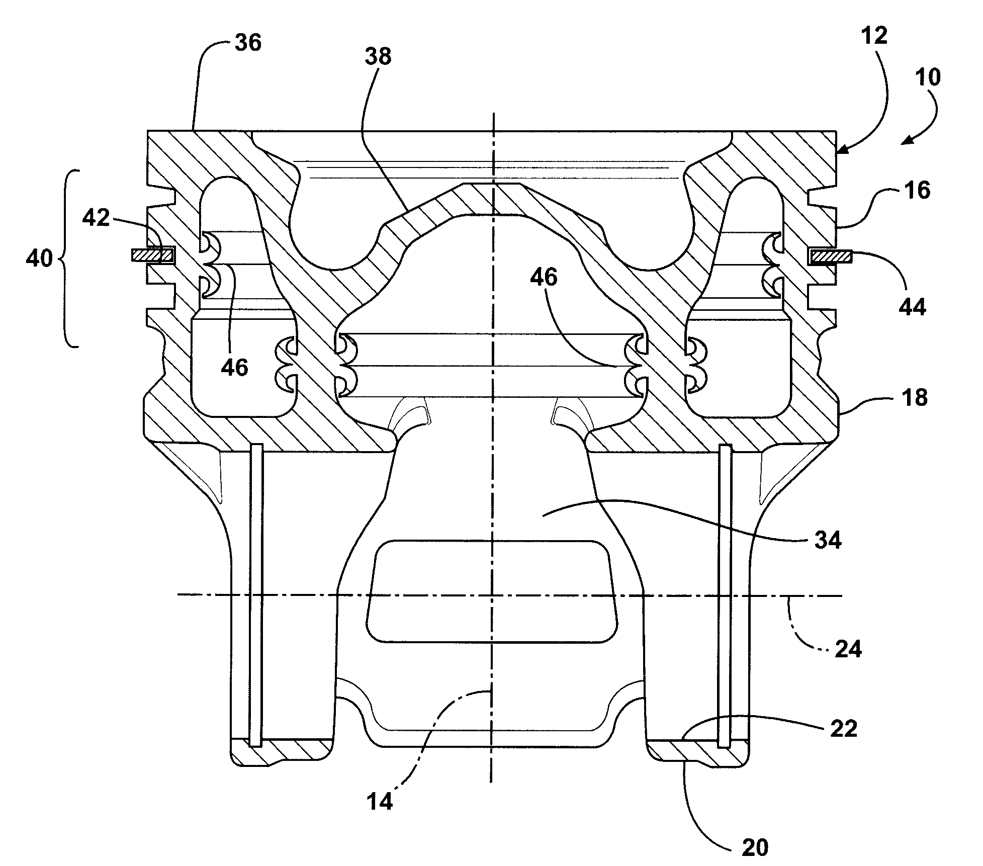
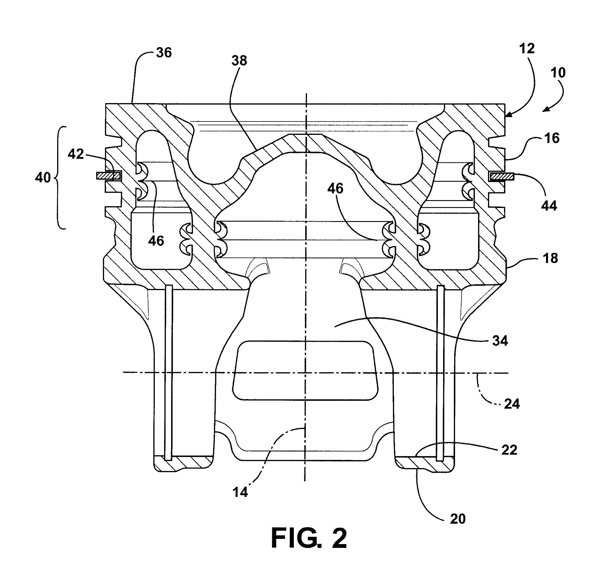
[0024]Referring in more detail to the drawings, FIGS. 1 and 2 illustrate a piston 10 constructed according to one presently preferred embodiment of the invention for reciprocating movement in a cylinder bore (not shown) of an internal combustion engine, such as a diesel engine. The piston 10 has a body 12, either cast or forged, or by any other process of manufacture, extending along a central axis 14 along which the piston 10 reciprocates in the cylinder bore. The body 12 is represented, by way of example and without limitation, as having an upper crown 16 joined to a lower crown 18 having a pair of pin bosses 20 depending from the upper crown to provide laterally spaced pin bores 22 aligned along a pin bore axis 24 that extends generally transverse to the central axis 14. By way of example and without limitation, the pin bosses 20 are joined to laterally spaced skirt portions 26 via strut portions 28, thereby forming a so called “monobloc” piston wherein the skirt portions 26 are ...


PUM


Abstract

A piston has a pair of diametrically opposite skirt portions each having an opening providing fluid communication between an outer surface of the skirt portions and an internal cavity. The openings provide the outer surfaces of the skirt portions with a circumferentially extending upper band portion above a horizontal plane extending through a pin bore axis and a circumferentially extending lower band portion below the horizontal plane.

Description

CROSS-REFERENCE TO RELATED APPLICATION[0001]This application claims the benefit of U.S. Provisional Application Ser. No. 60 / 955,423, filed Aug. 13, 2007, which is incorporated herein by reference in its entirety.BACKGROUND OF THE INVENTION[0002]1. Technical Field[0003]This invention relates generally to internal combustion engines, and more particularly to pistons for heavy duty diesel engines.[0004]2. Related Art[0005]It is known that internal combustion engines, and particularly diesel engines, experience high oil consumption that leads to undesirable exhaust emissions. In addition, with the oil consumption comes carbon build-up on surfaces of pistons, particularly in the top land area, including in the annular ring grooves. As such, the ring movements can be restricted by the carbon build-up, thereby diminishing the effectiveness of the rings to properly seal the combustion gas and control oil consumption, thereby resulting in increased oil blow-by, reduced engine performance, re...

Claims


Application Information

Patent Timeline
Patent Type & Authority Applications(United States)
IPC IPC(8): F01B31/10
CPCF16J1/04F02F3/003
Inventor AZEVEDO, MIGUEL
Owner TENNECO
Learn More