Deployment apparatus for submerged power plant

a technology for power plants and submerged pga, which is applied in the direction of electric generator control, special purpose vessels, hoisting equipment, etc., and can solve the problems of difficult to see, significant effect on the cost of maintaining the entire machine over its lifetime, and considerable difficulty in deploying a submerged pga than it is to retriev

Active Publication Date: 2009-02-19
SABELLA
View PDF7 Cites 41 Cited by
  • Summary
  • Abstract
  • Description
  • Claims
  • Application Information

AI Technical Summary

Benefits of technology

[0009]Water current or wave generating devices are, by their very nature, deployed in extreme marine environments where weather and sea state conditions can often make marine operations difficult. The speed and simplicity of the method of deployment and retrieval of the PGA, and in particular the tolerance of this method to moderately bad weather and sea state conditions are therefore particularly important.
[0011]Retrieval of the PGA is easier because, once detached, the PGA can be raised off the support structure quickly without the need for careful control of its alignment.
[0014]A telescopic tube normally housed inside the support structure can be raised to the surface to allow the PGA to be fitted to it for deployment. This telescopic tube guides the negatively buoyant PGA straight up and down, to and from the surface. The weight of the PGA and the telescopic tube is supported by a deck-mounted winch / crane on a surface vessel. This method addresses the issue of position control of the PGA, allowing the lifting and lowering operations to be performed more quickly and easily. The scheme still requires vessel-mounted heavy lifting equipment, and there is a considerable overhead associated with the telescopic tube, which is only used on an occasional basis. There is also the possibility of the telescopic tube jamming, with the associated risk that the machine is left in a potentially dangerous state should weather conditions deteriorate.

Problems solved by technology

This can have a significant effect on the cost of maintaining the entire machine over its lifetime.
Water current or wave generating devices are, by their very nature, deployed in extreme marine environments where weather and sea state conditions can often make marine operations difficult.
Generally speaking, it is considerably more difficult to deploy a submerged PGA than it is to retrieve it.
The deployment requires accurate alignment and attachment of the PGA with the support structure underwater, where it is difficult to see what is happening and where accurate control of the PGA position may be difficult to achieve.
The vessel required to lower / raise a heavy PGA is expensive and may not be available at short notice.
The constant motion of the vessel on the surface can pose problems for the position control of the PGA, particularly during its deployment.A telescopic tube normally housed inside the support structure can be raised to the surface to allow the PGA to be fitted to it for deployment.
The scheme still requires vessel-mounted heavy lifting equipment, and there is a considerable overhead associated with the telescopic tube, which is only used on an occasional basis.
There is also the possibility of the telescopic tube jamming, with the associated risk that the machine is left in a potentially dangerous state should weather conditions deteriorate.Guide wires running from a surface vessel down to a support structure are used to guide the PGA as it is lowered and raised through the water column.
The correct tensioning of these guide wires from the surface vessel requires accurate position holding and possibly heave compensation equipment, which is expensive.
In the case of a water current generating machine where there is only a short period of relatively slack water available, the deployment and recovery of the guide wires is a time-consuming operation and there may be insufficient time.A buoyant but submerged PGA, attached to the seabed by mooring cables, is raised and lowered using a crane / winch mounted on the deck of a surface vessel.
These issues pose significant practical difficulties in the underwater environment, particularly in terms of accessing such equipment for maintenance.

Method used


Image

  • Deployment apparatus for submerged power plant
  • Deployment apparatus for submerged power plant
  • Deployment apparatus for submerged power plant

Examples


Embodiment Construction

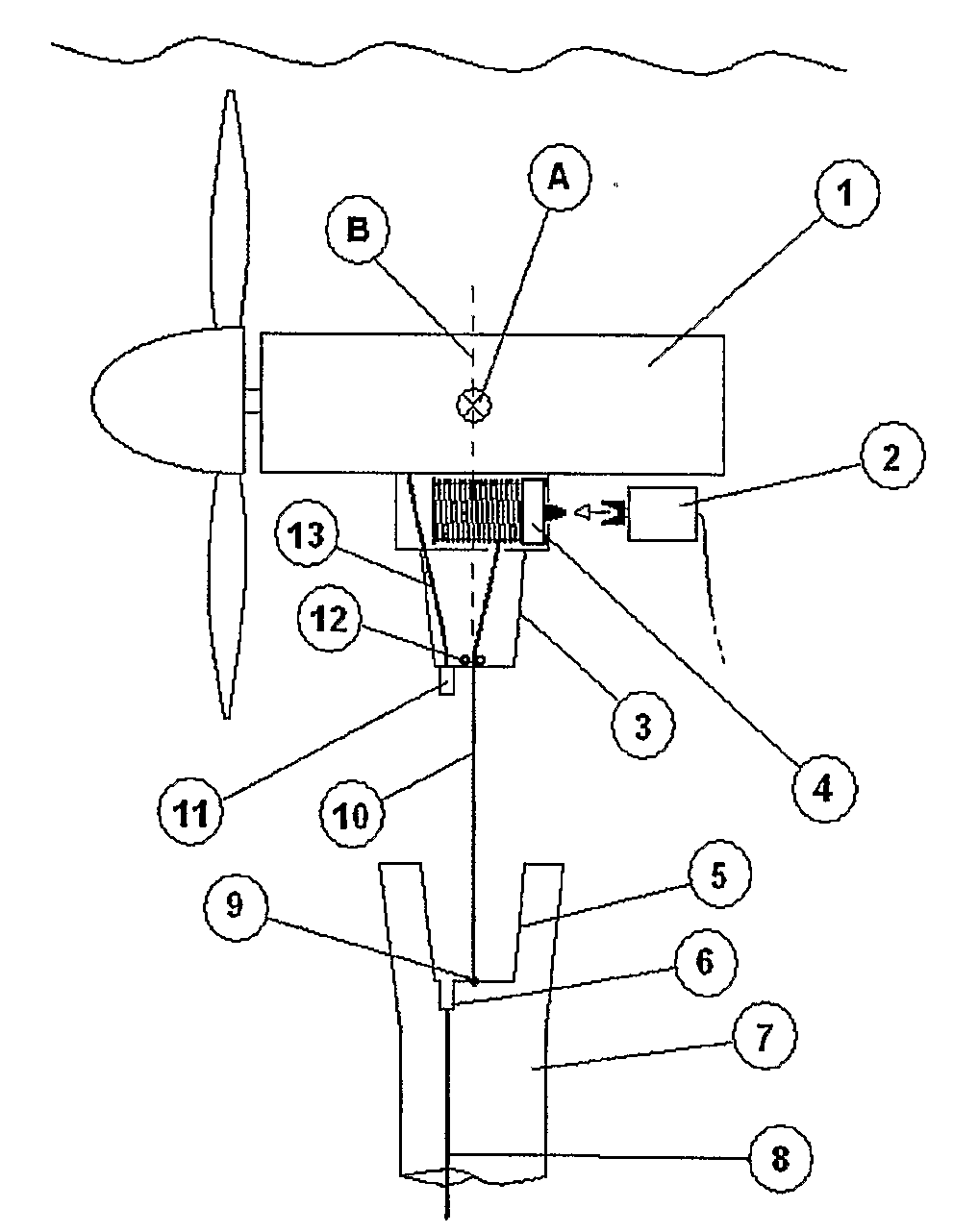
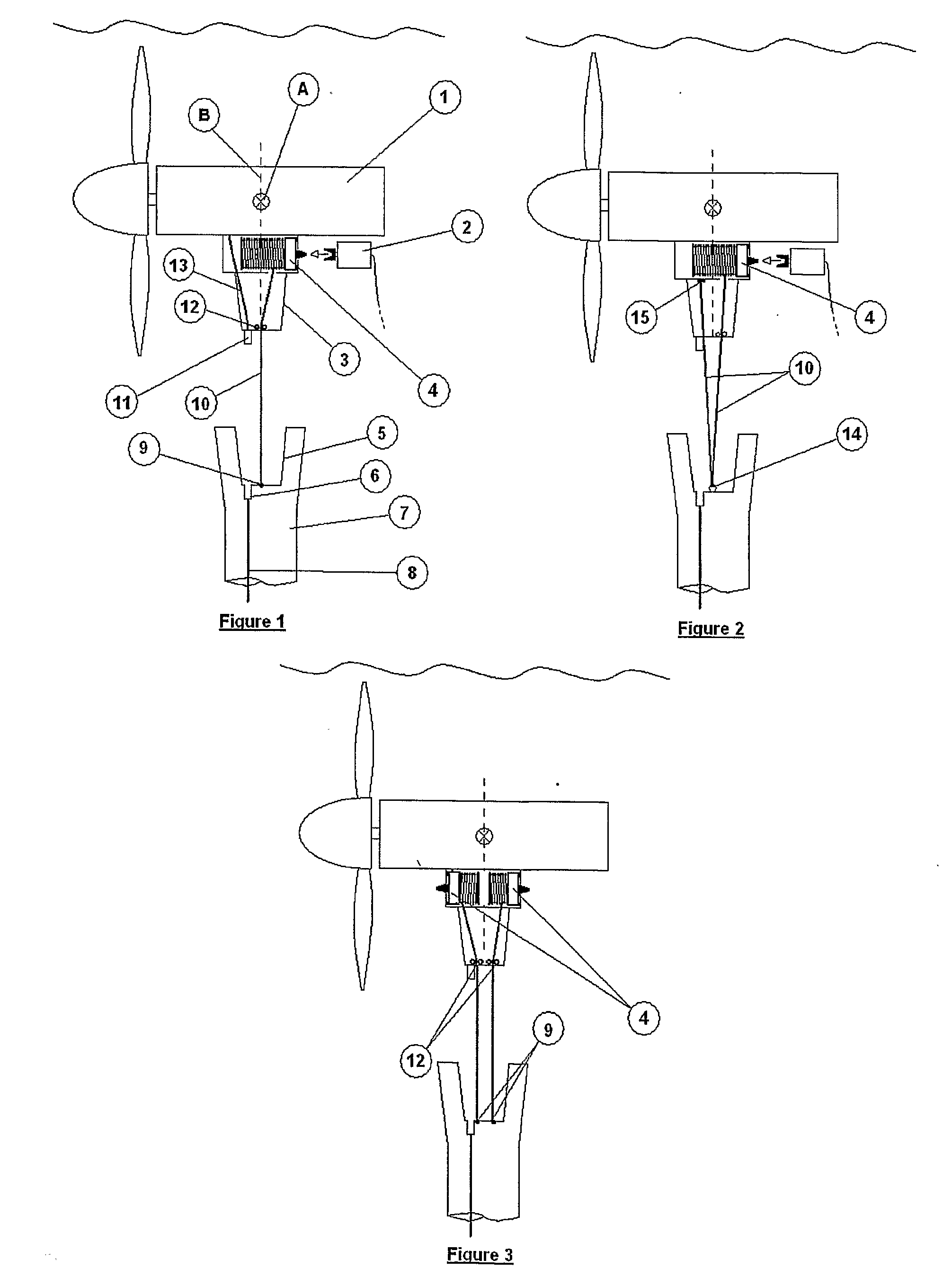
[0025]The power generating equipment shown in FIG. 1 comprises a buoyant power generating apparatus 1 (PGA). In this instance, the PGA 1 is a water current generating device; however, it is to be understood that the invention is equally applicable to any form of power generating apparatus. Also shown in FIG. 1 is part of a support structure 7, which is positioned on the bed of a body of water. The support structure 7 comprises the female part 5 of an alignment means, while the PGA 1 comprises the male part 3 of the alignment means. It will be appreciated that the female and male parts of the alignment means could equally be positioned in the opposite orientation without affecting operation of the invention.

[0026]The term “alignment means” as used in this specification is intended to encompass any means by which the PGA 1 and support structure 7 may be brought together in a defined alignment. For example, such alignment means may not have male and female parts as described herein, bu...


PUM


Abstract

Power generating equipment comprising a buoyant power generating apparatus and a support structure for the power generating apparatus, which support structure, in use, is disposed on the bed of a body of water, the power generating apparatus comprising a motor-driven winching device having a tether which is connectable at its free end to the support structure whereby retraction of the tether causes the power generating apparatus to be drawn downwardly through the body of water into engagement with the support structure, the power generating apparatus and the support structure being provided with means for aligning and latching the power generating apparatus with respect to the support structure upon engagement with the support structure.

Description

[0001]This invention relates to the deployment and retrieval of submerged power generating apparatus designed to generate electricity from tidal currents or ocean waves.[0002]A key aspect in the design of water current and wave generating equipment is the method by which the power generating apparatus (PGA) is periodically accessed for inspection and maintenance, and deployed again for operation. This can have a significant effect on the cost of maintaining the entire machine over its lifetime.[0003]Installations in which the PGA is fully submerged during normal operation and must on occasion be brought to the surface for inspection / maintenance can be divided into two categories:[0004]1. Schemes employing a surface breaking support structure (such as a mono-pile). The structure itself is used as a guide to allow the PGA to be raised to the surface using some form of mechanical lifting device (e.g. hydraulic rams, surface mounted winch) or possibly using the force of buoyancy.[0005]2...

Claims


Application Information

Patent Timeline
Patent Type & Authority Applications(United States)
IPC IPC(8): F03B13/10F03B13/26B63B27/08F03B17/06
CPCB63B2035/4466E02B2017/0091F03B13/264F03B17/061Y02E10/28F05B2230/61F05B2240/90F05B2240/97F05B2230/604Y02E10/30Y02P70/50B66D1/60F03B13/10Y02E10/20
Inventor GIBBERD, GEORGEHUXLEY-REYNARD, CHRISTOPHERLAKE, TANIA
Owner SABELLA
Why Eureka
Try Eureka