Preparing polysilicon using a bell-
jar type reactor based on electrical resistance heating cannot be executed in a continuous manner because there is a limit in increaseing the rod
diameter according to silicon deposition.
In addition, the deposition efficiency is poor because the surface area required for silicon deposition is restricted and also excessive thermal loss results in high
power consumption per
unit volume of the product.
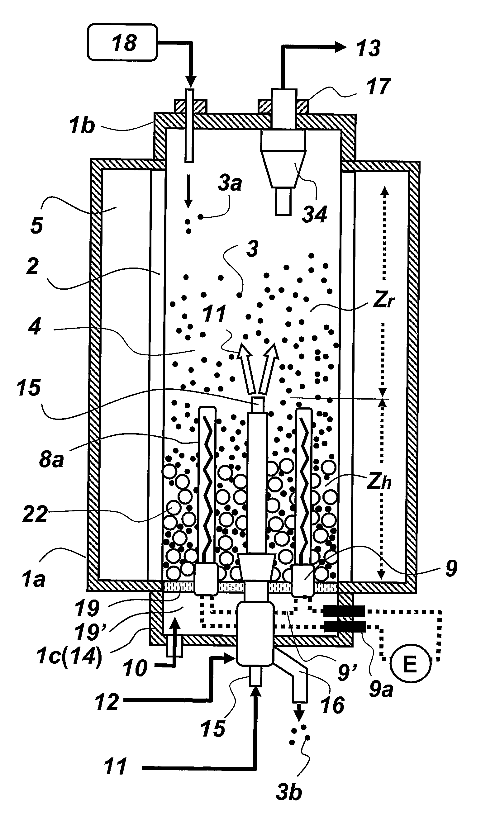
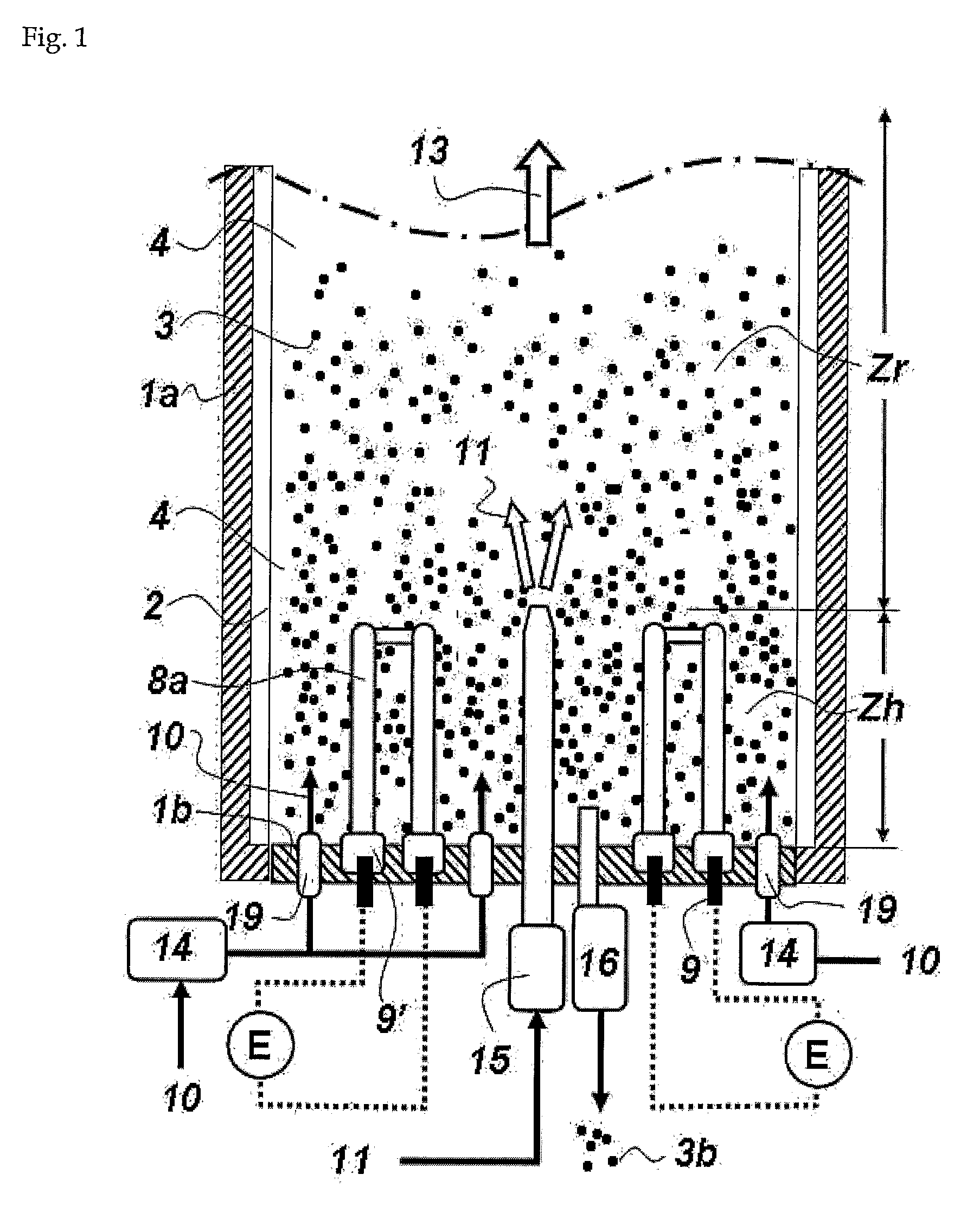
One of the most difficult steps in the continuous or semi-
continuous production of granular polysilicon using the fluidized
bed reactor is to heat the silicon particles in order to maintain the temperature required for the deposition.
The following problems are involved in heating the silicon particles in order to maintain the temperature required for the deposition reaction, while minimizing
impurity contamination of the silicon particles within the fluidized
bed reactor.
But, since silicon deposition occurs on the wall of the reaction-
gas heating means and the silicon deposit becomes accumulated as operation proceeds, the reaction gas cannot be sufficiently preheated before being supplied into the fluidized bed reactor.
It is therefore difficult to sufficiently heat the silicon particles by the conventional method of heating the walls of the reactor, and also it is impossible to operate the reactor stably for a long period of time.
In addition, few methods are available that enable the effective heating of the silicon particles while minimizing
impurity contamination.
But, this method has the following problems.
Because the partitioning means, which partition the reaction zone and the heating zone concentrically, has a
diameter smaller than the outer
diameter of the heating zone, silicon deposition and accumulation occur severely on the inner surface of the partitioning means which is exposed to the reaction zone, making it difficult to operate the reactor for a long period of time.
Also, since the circulation of the silicon particles along the circumferential direction is non-uniform, the method is not suitable for a large-scale production.
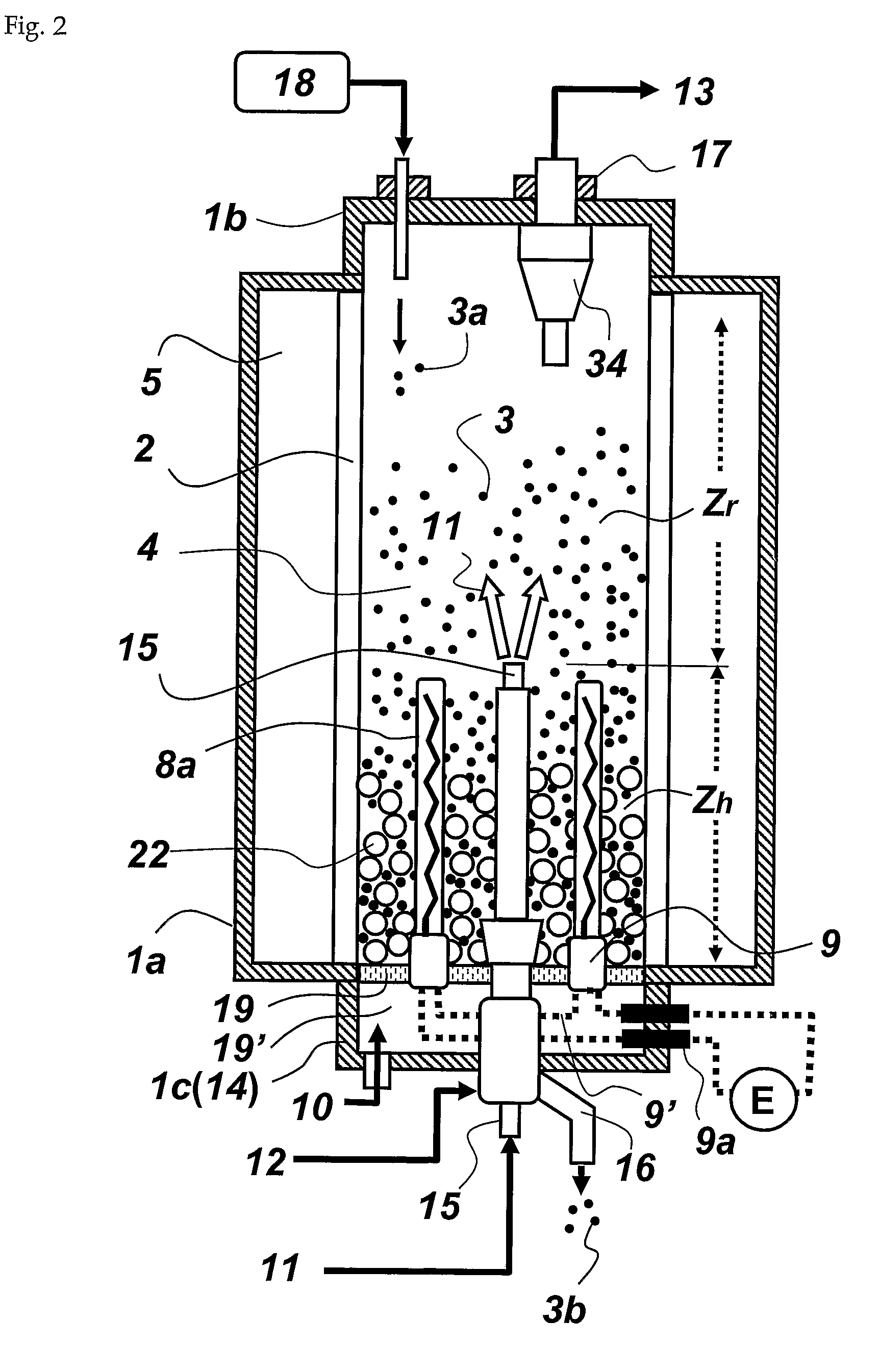
However, considering the productivity problem of the fluidized bed reactor, or the fact that it is difficult to maintain the bed of silicon particles at a predetermined
reaction temperature for large-sized reactors, a method capable of heating the heating zone more efficiently is required for the large-scale production of polysilicon using a fluidized bed reactor.
Further, because much energy is used to heat the fast flowing fluidizing gas in the heating zone requires, the heating of silicon particles becomes inefficient.
But, with this method, it is difficult to uniformly mix the particles while minimizing the
temperature difference of the two zones in a large-sized reactor.
Unlike other components commonly used in chemical processes, there is restriction in
material selection of the components of the fluidized bed reactor.
Because of irregular vibration and severe stress caused by the movement of silicon particles, the reactor tube is vulnerable to
mechanical impact.
Thus, the periodical application of physical
impact to the bed of silicon particles using the pulsing device as disclosed in U.S. Pat. No. 6,827,786 may significantly impair the stability of the reactor tube and make the safe, sustained operation of the fluidized bed reactor difficult.

