Holey fiber taper with selective transmission for fiber optic sensors and method for manufacturing the same

a fiber optic sensor and selective transmission technology, applied in the field of fiber optic devices using microstructured optical fibers, can solve the problems of inconvenient or impractical processing, and achieve the effect of reducing the waist diameter of the taper and increasing the length of the taper

Inactive Publication Date: 2009-02-26
MINKOVICH VLADIMIR PETROVICH +2
View PDF7 Cites 23 Cited by
  • Summary
  • Abstract
  • Description
  • Claims
  • Application Information

AI Technical Summary

Benefits of technology

[0006]According to the first aspect of the invention, reflected in FIG. 1(b), a nonadiabatic tapered single material HF structure with gradually collapsed air holes is provided. For the fabrication of the structure a HF is used, which consist of a pure silica core surrounded by pure silica cladding with a regular array of air holes that run inside the cladding along the length of the fiber. The holes are also arranged in a hexagonal structure around the core. For example, a large-core, single-mode HF, see FIG. 1(a), with a few rings of air-holes in the cladding that is described in more detail in [12] can be used. The claimed nonadiabatic tapered single material HF structure [see FIG. 1(b)] consists of two untapered holey fibers at z<−ZL and z>ZL, two gradually tapered regions −ZL to −ZW and ZW to ZL, and a cylindrical waist region −ZW to ZW. In the region −ZC to ZC, the air holes are fully collapsed. In the regions −ZL to −ZC and ZL to ZC, gradual collapsing of air holes occurs. The transmission spectrum of the taper exhibits a series of peaks. The number of the peaks increases as the diameter of the taper waist is reduced or the length of the taper is increased. Also the peaks become sharper for the same reasons. Such interference peaks are sensitive to the external environment and that allows using our invention as a sensor for measuring many parameters.

Problems solved by technology

In some situations, such a process may be inconvenient or impractical.

Method used


Image

  • Holey fiber taper with selective transmission for fiber optic sensors and method for manufacturing the same
  • Holey fiber taper with selective transmission for fiber optic sensors and method for manufacturing the same
  • Holey fiber taper with selective transmission for fiber optic sensors and method for manufacturing the same

Examples


example 1

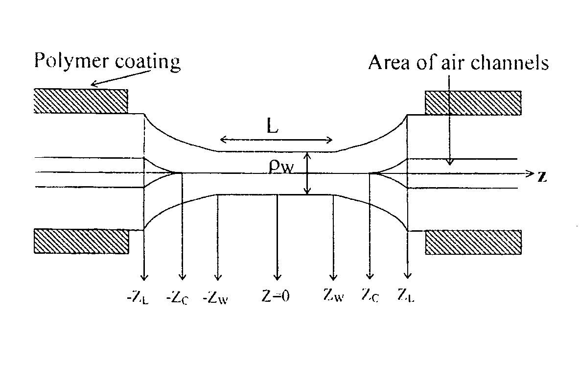
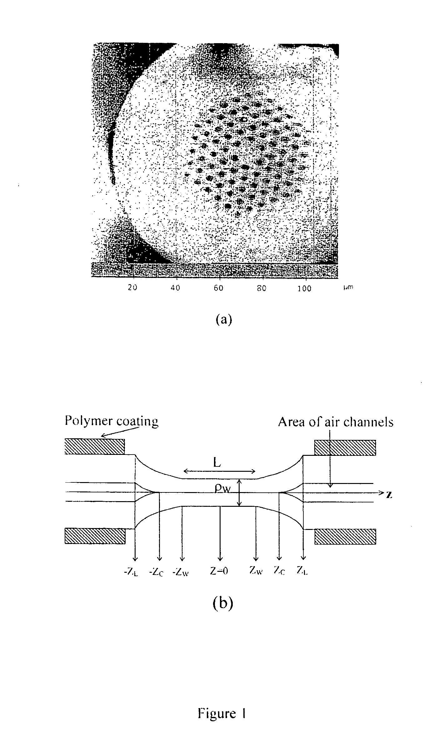
[0021]The fiber employed to fabricate the tapers was a large core single-mode, made from single material, HF with a solid silica core surrounded by a few air holes in the cladding. The fabrication and properties of such a fiber are described in detail in [12]. As one can see from FIG. 1(a) the untapered single material HF consists of four full rings of air holes in hexagonal pattern (the fifth ring is partially collapsed). The outer diameter of the HF is 125 μm, the diameter of the solid core is 11 μm, the average hole diameter d is 2.7 μm, and the average hole spacing, or pitch, Λ is 5.45 μm. To obtain a nonadiabatic tapered single material HF structure we first inserted the HF into a standard single-mode fiber by fusion splicing both fibers. This allowed us to seal the ends of the HF. The length of the HF was chosen to be about 30 cm. Then the HF is slowly stretched while it was being heated with an oscillating high-temperature flame torch. The temperature of the flame was approxi...

example 2

[0025]By using the same fiber, and the same tapering process as in example 1, a single material HF taper with waist diameter ρw=28 μm and L=5 mm was fabricated. FIG. 7 shows the normalized transmission spectra of the HF before (dotted line) and after (continuous line) the nonadiabatic tapering process. The measurements were carried in a measuring setup consisting of a LED, with peak emission at 1540 nm and 40 nm of spectral with, and an optical spectrum analyzer with resolution of 0.1 nm. It is possible to see from the figure that the transmission of the untapered single material HF is basically the output spectrum of the LED. However, the spectrum of the 28 μm-thick taper exhibits a series of peaks, two of which are higher than the others. For this taper it was investigated the shift of the interference peaks caused by longitudinal strain. The HF was fixed between two displacement mechanical mounts, with the tapered section in the middle. Then the fiber was stretched using the cali...


PUM

PropertyMeasurementUnit
temperatureaaaaaaaaaa
temperaturesaaaaaaaaaa
hole diameteraaaaaaaaaa

Abstract

Large-mode-area single material holey fiber tapers with collapsed by nonadiabatic process air holes in the waist for fiber optic sensors and a method for manufacturing these tapers are claimed. The gradual collapsing of the holes is achieved by tapering the fibers with a “slow-and-hot” method. This nonadiabatic process makes the fundamental mode of the holey fiber to couple to multiple modes of the solid taper waist. Owing to the beating between the modes, the transmission spectra of the tapered single material holey fibers exhibit several interference peaks. That means the all-fiber Mach-Zehnder type interferometer is formed in a holey fiber such a way. The multiple peaks, combined with a fitting algorithm, allow high-accuracy refractometric measurements, temperature-independent strain measurements, measurements of high temperature and may be used for measuring many others parameters.

Description

BACKGROUND OF THE INVENTION [0001]The present invention relates to fiber optic devices using microstructured optical fibers, also known as photonic crystal or holey fibers (HFs), which consist of a single material. The HF is a new class of optical fibers with no conventional propagation characteristics that have been largely investigated. Usually HFs consist of a pure silica core surrounded by pure silica cladding with a regular array of air holes that run inside of the cladding along the length of the fiber and are arranged in a hexagonal structure around the core [1,2]. HFs are characterized in terms of hole size and hole spacing. The holes are usually periodically spaced, the period being termed as “pitch”, Λ. The holes are usually circular and can be characterized by a diameter, d.[0002]The structure of single material HFs enables new possibilities for optical sensing and provides an efficient method to exploit the interaction of the guided light with different gases, liquids, o...

Claims


Application Information

Patent Timeline
Patent Type & Authority Applications(United States)
IPC IPC(8): G02B6/02C03B7/01
CPCG02B6/02009G02B6/02376G02B6/02347G02B6/02333
Inventor MINKOVICH, VLADIMIR PETROVICHVILLA-TORO BERNARDO, AUGUSTIN JOELHERNANDEZ, DAVID MONZON
Owner MINKOVICH VLADIMIR PETROVICH
Why Eureka
Try Eureka