Electrode configurations for directional leads

a directional lead and electrode configuration technology, applied in the field of medical devices, can solve the problems of undesirable phrenic nerve stimulation, non-optimal lv pacing electrode placement of lv lead electrodes, and general undesirable stimulation of neck muscles, and achieve the effect of preventing the propagation of electrical fields

Inactive Publication Date: 2009-02-26
MEDTRONIC INC
View PDF100 Cites 49 Cited by
  • Summary
  • Abstract
  • Description
  • Claims
  • Application Information

AI Technical Summary

Benefits of technology

[0007]In general, the present disclosure is directed toward delivering electrical stimulation using electrode segments in an anodal shielding configuration. For example, an implantable medical device (IMD) may configure a first electrode segment of an electrical stimulation lead as a cathode and two adjacent electrode segments of the lead, which may be on opposite sides of the first electrode segment, as anodes. This configuration may be referred to as an “anodal shielding” configuration in the sense that the anodes act as a shield around the cathode to substantially prevent propagation of the electrical field from the cathode to tissue that is beyond the anodes, e.g., tissue on an opposite side of the anode than the cathode. Anodal shielding may focus the electrical field propagating from the lead in a particular transverse direction relative to a longitudinal axis of the lead. Anodal shielding may also focus the electrical field propagating from the lead at a particular longitudinal direction. In this manner, anodal shielding may be useful in directing a stimulation field toward a target site and / or away from an undesirable site.
[0016]Electrode configuration in a directional lead may be particularly useful in left ventricle (LV) pacing applications. An IMD may configure electrodes segments of a lead in an anodal shielding configuration to direct the electrical field toward the myocardium and away from the phrenic nerve. Directing the electrical field towards the myocardium may reduce the amount of energy required for tissue capture of the myocardium for pacing therapies and, consequently, increase battery life. In addition, directing the electrical stimulation field towards the myocardium may reduce the likelihood of phrenic nerve stimulation, because the electrical stimulation field will generally be directed away from the phrenic nerve.
[0017]As another example, electrode configuration in a directional lead may be useful in stimulation of the vagus nerve. The vagus nerve is positioned proximate to muscles of the neck, which may inadvertently be stimulated along with the vagus nerve. Anodal shielding may control the direction and extent of propagation of the electrical field and aid in preventing stimulation of the neck muscles.
[0018]The electric fields produced using at least two adjacent electrode segments as cathodes may be combined with the techniques utilizing anodal shielding. A single IMD may optionally configure electrode segments using a single electrode segment as a cathode, using multiple electrode segments as cathodes, as well configuring electrode segments in anodal shielding configuration. An IMD that provides each of these techniques may be able to more successfully direct a stimulation field toward a target site and / or away from an undesirable site.

Problems solved by technology

Phrenic nerve stimulation is generally undesirable during LV pacing therapy.
In some instances, the implantable lead may need to be specifically positioned to avoid phrenic nerve stimulation during LV pacing therapy, which may result in placing the electrodes of the LV lead at a non-optimal site for LV pacing.
Stimulation of neck muscles is generally undesirable during therapeutic vagal neurostimulation.

Method used


Image

  • Electrode configurations for directional leads
  • Electrode configurations for directional leads
  • Electrode configurations for directional leads

Examples


Embodiment Construction

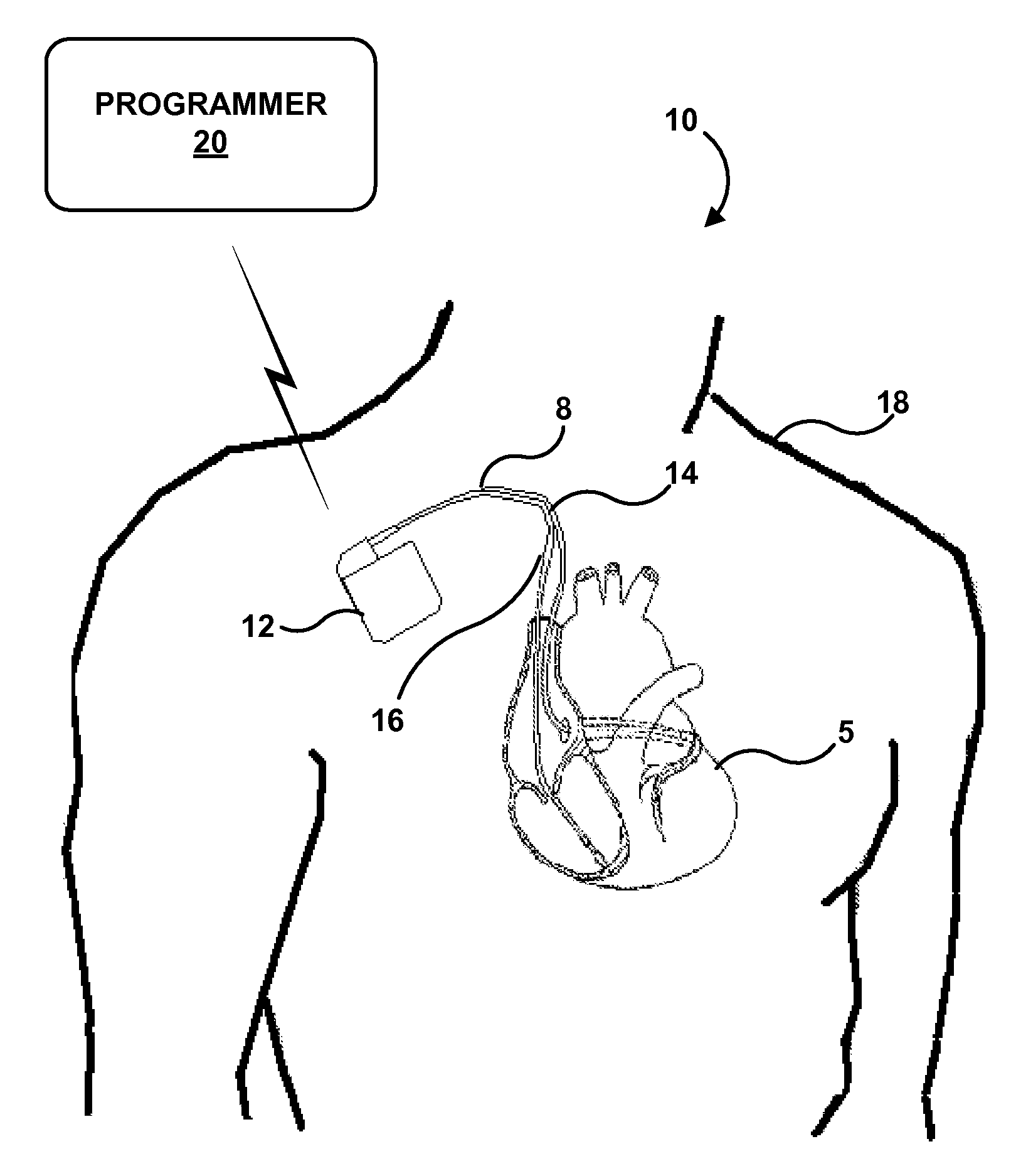
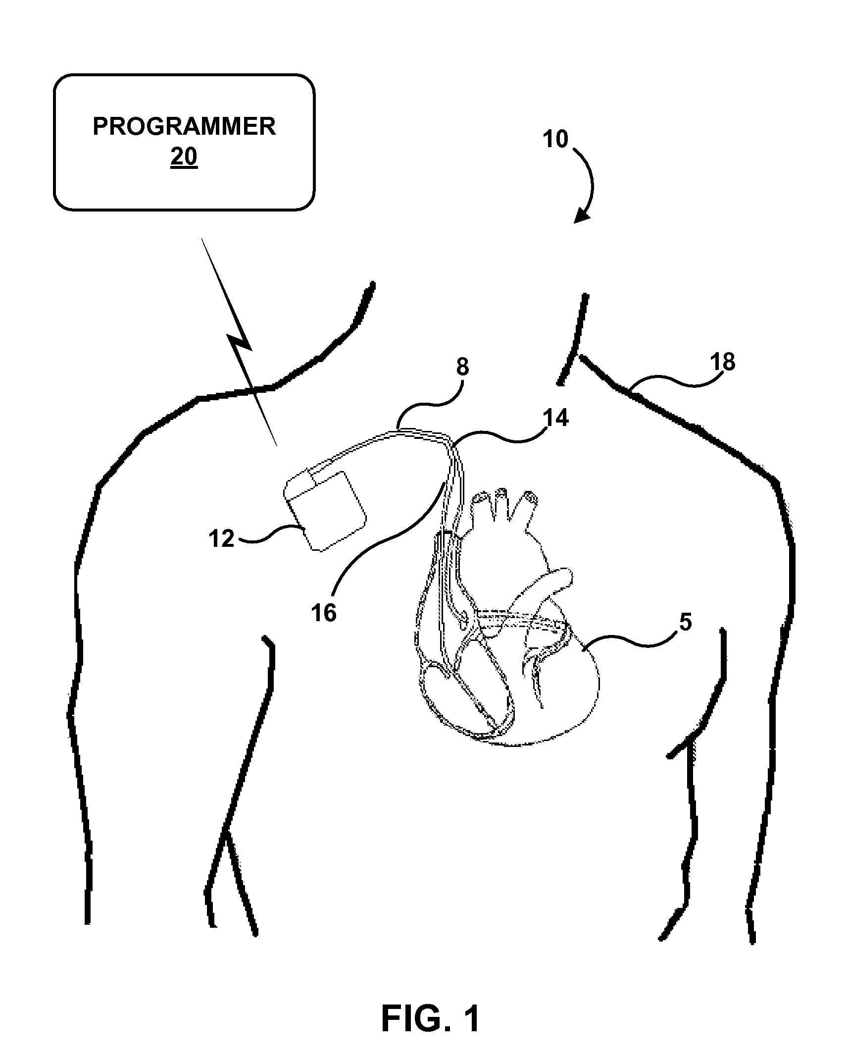
[0036]While the description primarily refers to implantable medical leads and implantable medical devices, such as pacemakers and pacemaker-cardioverter-defibrillators, that deliver stimulation therapy to a patient's heart, the features and techniques described herein are useful in other types of medical device systems, which may include other types of implantable medical leads and implantable medical devices. For example, the features and techniques described herein may be used in systems with medical devices that deliver neurostimulation to the vagus nerve. As other examples, the features and techniques described herein may be embodied in systems that deliver other types of neurostimulation therapy (e.g., spinal cord stimulation or deep brain stimulation), stimulation of one or more muscles or muscle groups, stimulation of one or more organs such as gastric system stimulation, stimulation concomitant to gene therapy, and, in general, stimulation of any tissue of a patient.

[0037]In...


PUM


Abstract

A system includes an implantable electrical stimulation lead configured for intravenous introduction into a vessel proximate to a heart and an electrical stimulator. The lead comprises a lead body and at least three electrode segments. The electrical stimulator is coupled to the electrode segments and configures a first of the electrode segments as a first anode, a second of the electrode segments as a cathode, and a third of the electrode segments as a second anode, and delivers electrical stimulation to the heart via the cathode and first and second anodes. Additional techniques for delivering electrical stimulation include using multiple electrode segments as cathodes and electrically isolating other electrode segments. Other examples are directed to techniques for directing electrical therapy to a vagus nerve of a patient.

Description

[0001]This application claims the benefit of U.S. Provisional Application No. 60 / 956,832, filed Aug. 20, 2007, U.S. Provisional Application No. 60 / 956,868, filed Aug. 20, 2007 and U.S. Provisional Application No. 61 / 049,232, filed Apr. 30, 2008, each of which are hereby incorporated by reference.TECHNICAL FIELD[0002]The present disclosure relates to medical devices, more particularly to delivery of electrical stimulation via implantable medical leads.BACKGROUND[0003]In the medical field, a wide variety of medical devices use implantable leads. For example, implantable cardiac pacemakers provide therapeutic stimulation to the heart by delivering pacing, cardioversion, or defibrillation pulses via implantable leads. Implantable cardiac pacemakers deliver such pulses to the heart via electrodes disposed on the leads, e.g., near distal ends of the leads. Implantable medical leads may be configured to allow electrodes to be positioned at desired cardiac locations so that the pacemaker ca...

Claims


Application Information

Patent Timeline
Patent Type & Authority Applications(United States)
IPC IPC(8): A61N1/362A61N1/05
CPCA61N1/0534A61N1/0551A61N1/056A61N2001/0585A61N1/368A61N1/3684A61N1/36114A61N1/36842
Inventor BOURN, DAVID WAYNESOMMER, JOHN L.MARSHALL, MARK T.EGGEN, MICHAEL D.MIYAZAWA, GABRIELA C.
Owner MEDTRONIC INC
Why Eureka
Try Eureka