Autonomous and automatic landing system for drones

a drone and automatic technology, applied in the field of aircraft, can solve the problems of unfavorable rapid deployment of systems on landing sites, inconvenient use and recovery of drones, and inability to provide gps service in high-accuracy mode, and achieves less cost, simple design, and greater geographic robustness.

Active Publication Date: 2009-02-26
THALES SA
View PDF14 Cites 71 Cited by
  • Summary
  • Abstract
  • Description
  • Claims
  • Application Information

AI Technical Summary

Benefits of technology

[0019]The proposed device advantageously presents a greater robustness to geographic and climatic conditions than the existing devices. It also presents the advantage of being simpler to design and therefore less costly. It also advantageously has the capacity to simultaneously guide several aircraft to the landing zone.

Problems solved by technology

Such systems are unlikely to be deployed rapidly on a landing site because they require relatively large infrastructures to be put in place on the ground.
They are therefore ill-suited to the use and recovery of drones.
However, this solution poses the problem of the availability or the continuity of GPS service in high-accuracy mode.
Furthermore, the vulnerability of the GPS systems in the presence of scramblers is well known.
This type of system is, however, sophisticated and therefore costly.
In the approach phase, after all, the guidance constraints to keep the target in the radar beam are very significant.
The risks of stalling and therefore of interrupting the guidance are significant.
When the link is critical, an interruption of the tracking can result in erratic guidance with consequences that can be fatal for the aircraft.
Furthermore, these solutions are generally costly and have limitations concerning in particular the servo-controlling of the transmitted beam on the position of the target in its approach movement, mechanical limitations that originate in the servo-controls.
Also, regarding detection systems servo-controlled on a particular target, these systems are ill-suited to the simultaneous guidance of several drones approaching a landing zone.

Method used


Image

  • Autonomous and automatic landing system for drones
  • Autonomous and automatic landing system for drones
  • Autonomous and automatic landing system for drones

Examples


Embodiment Construction

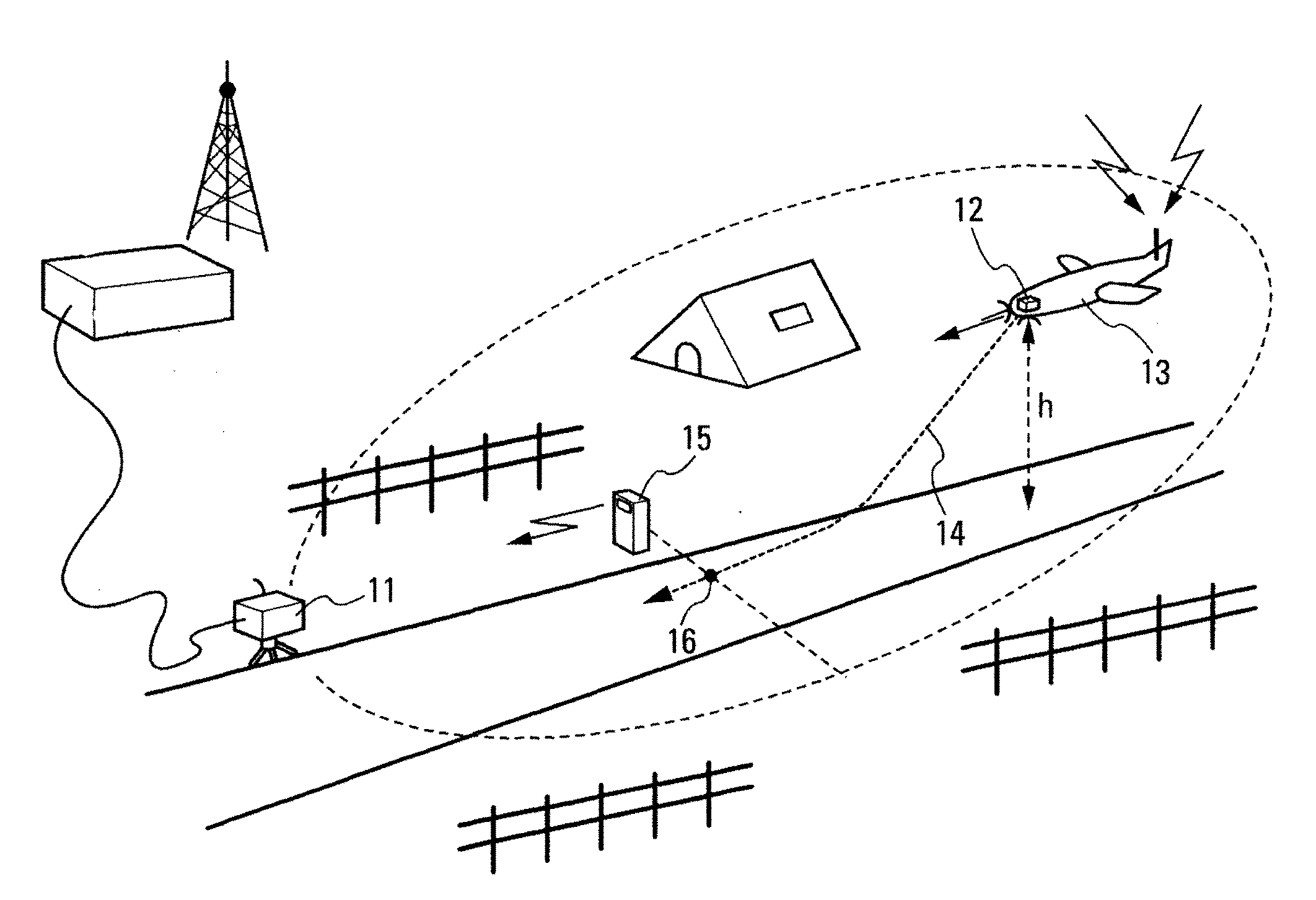
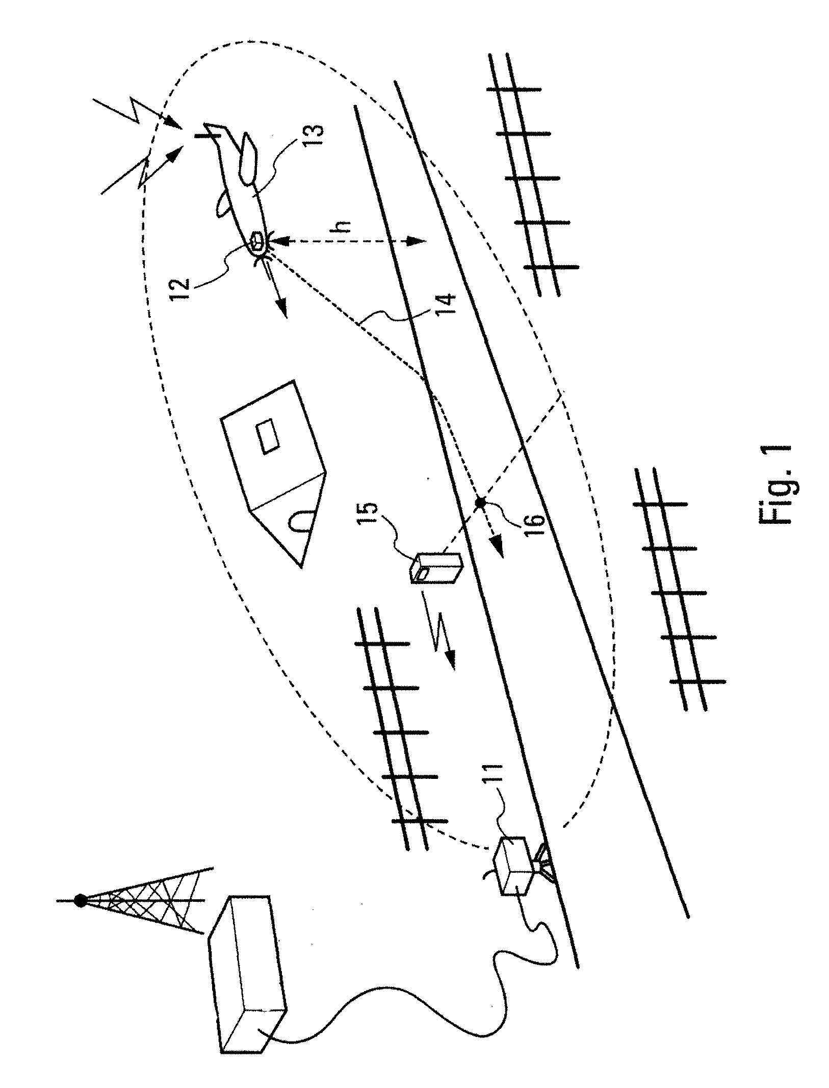
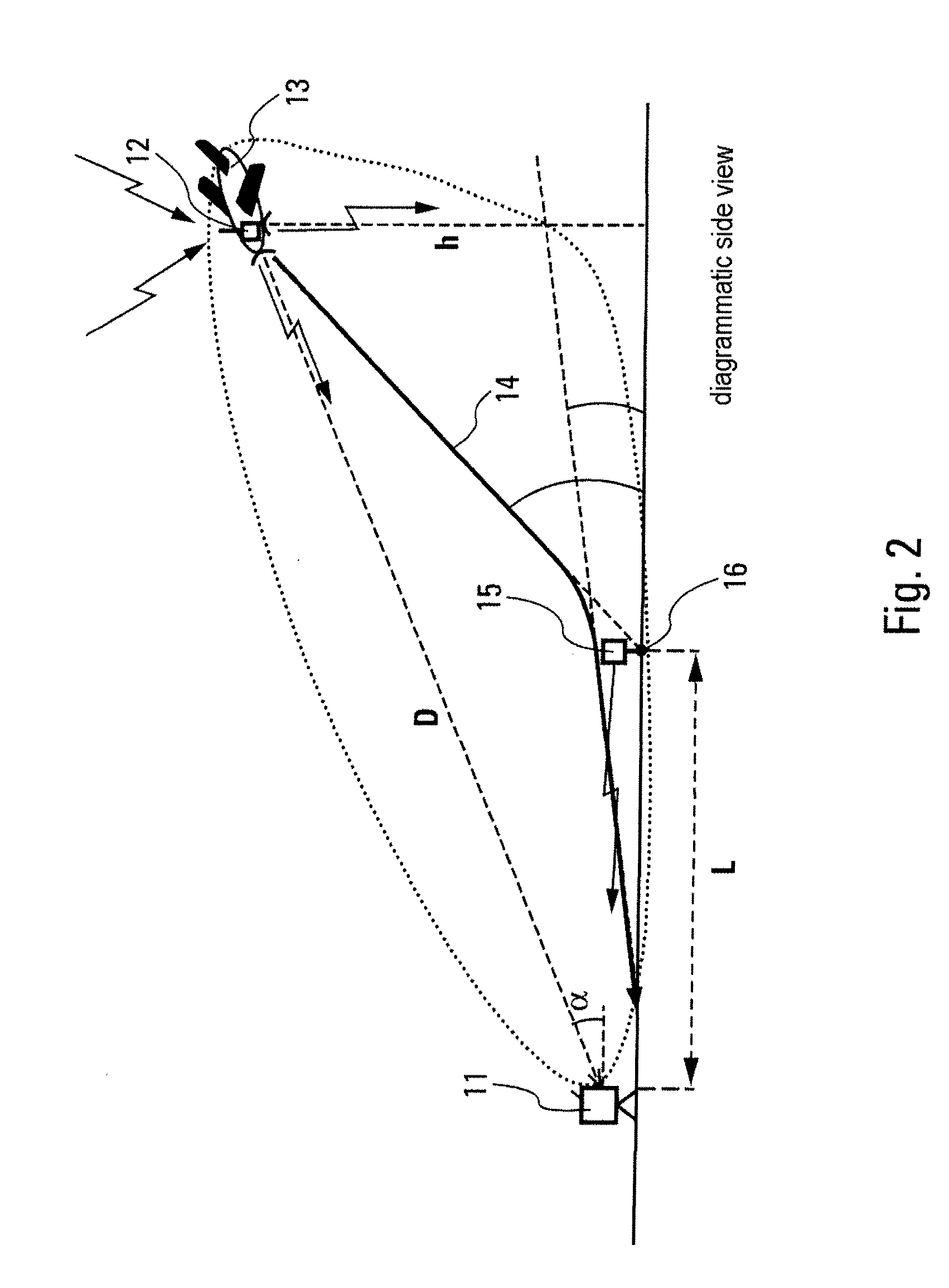
[0027]Referring firstly to FIGS. 1 to 3, these illustrate, by means of views from different angles, the principle of operation of the system according to the invention.

[0028]To automatically guide an aircraft in the landing phase, the system according to the invention mainly comprises a detecting and locating device 11, located on the ground, and a multifunction beacon 12 on board the aircraft 13.

[0029]The main function of the detecting device 11 is to periodically measure the altitude h of the aircraft 13 and the radial distance D which separates the aircraft from the point on which it is located. It also measures the direction and altitude differences that exist between the direction connecting this device to the aircraft and a reference direction, preferably parallel to the axis of the runway on which the aircraft is to land. For this, it for example applies ecartometry measurements, known from elsewhere, enabling it to determine the azimuth and the elevation relative to the guid...


PUM


Abstract

The invention relates to an automatic aircraft landing guidance system having an electromagnetic detecting and locating device, positioned on the ground and a first multifunction transmitting/receiving radiofrequency beacon, on board each guided aircraft and transmitting in particular a continuous wave. The detecting and locating device uses the continuous wave transmitted by the beacon to perform a passive locating intended to improve the accuracy of the measurement of the angular position of the aircraft. It also comprises means for generating and periodically transmitting to the aircraft, via the beacon, information enabling said aircraft to rejoin an optimum landing path from its position. The invention applies more particularly to the guidance of autonomous and automatic aircraft such as drones in the approach and landing phase.

Description

CROSS-REFERENCE TO RELATED APPLICATIONS[0001]The present Application is based on International Application No. PCT / EP2006 / 069198, filed on Dec. 1, 2006, which in turn corresponds to French Application No. 0512257, filed on Dec. 2, 2005, and priority is hereby claimed under 35 USC §119 based on these applications. Each of these applications are hereby incorporated by reference in their entirety into the present application.FIELD OF THE INVENTION[0002]The present invention relates to the field of aircraft and in particular the field of autonomous and automatic aircraft such as drones. It more particularly relates to the guidance of such aircraft in the approach and landing phase.BACKGROUND OF THE INVENTION[0003]Existing landing aid systems, enabling autonomous craft to land, are currently based on various technologies.[0004]It is possible firstly to use systems type-approved by civil aviation such as instrument landing systems (ILS) or microwave landing systems (MLS), and their milita...

Claims


Application Information

Patent Timeline
Patent Type & Authority Applications(United States)
IPC IPC(8): G05D1/00
CPCG01S11/10G01S13/003G05D1/0676G01S13/88G01S13/913G01S13/825
Inventor GARREC, PATRICKCORNIC, PASCAL
Owner THALES SA
Why Eureka
Try Eureka