Method and apparatus for dispensing fluids

a technology of fluid dispensing and fluid injection, applied in the direction of liquid handling, pliable tubular containers, instruments, etc., can solve the problems of waste of fluid, exacerbate recycling and disposal problems, and prevent the complete dispensing of fluid, etc., to achieve quick and easy engagement and release

Active Publication Date: 2009-03-05
ENTEGRIS INC
View PDF65 Cites 95 Cited by
  • Summary
  • Abstract
  • Description
  • Claims
  • Application Information

AI Technical Summary

Benefits of technology

[0009]Various aspects of the invention include inner and outer flexible containers disposed in a containment vessel for dispensing fluid from the container more efficiently and completely than in prior art devices. Other embodiments may include a cap assembly that cooperates with a dispense head for pressurization of the outer flexible container for extraction of the fluid from the inner flexible container. The cap may be configured with a key code device coded to identify the type of fluid contained in the containment vessel and cooperates only with dispense heads that are configured for compatible mating with the key code device. The dispense head may be configured with cams that engage with the cap for quick and easy engagement and release. The cams may be actuated by a handle that is contoured so that, when in the fully engaged position, no portion of the handle extends beyond the footprint of the containment vessel. The dispense head may also include a stem or dip tube that extends from the cap into the inner flexible container and having an inlet on the distal end through which the fluid is extracted. The dip tube may include a passage or groove formed on the exterior, providing a way for pockets of fluid otherwise trapped against the dip tube to drain downward for extraction through the dip tube inlet.
[0010]In one embodiment, an inner flexible container for containing the dispense fluid may comprise a member of a chemical resistant polymer, such as a fluoropolymer. For example, pin-hole free perfluoroalkoxy (PFA) material is desirable for containing chemicals such as photoresist due to inert molecular properties which prevent contamination or leakage of the fluid. The inner flexible container can be formed by sealing a dispensing fitment in a hole in the center of a rectangular, octagon, or other custom shaped sheet or member of PFA material. The PFA member may be folded in half such that the two halves can be sealed together at the edges of the open sides, forming the inner flexible container with the dispensing fitment located at the top of the container. The outer flexible container may comprise a separate outer fitment sealed to a hole proximate the center of two sheets (inner and outer members) of polyethylene (PE) or other flexible non-permeable material
[0015]An advantage of embodiment of the invention described above is that the pressurization fluid does not directly contact the dispensing container. Certain embodiments of the invention provide a barrier of material that is highly gas impermeable between the inner flexible container and the pressurization fluid. Experiments have demonstrated that the provision of the highly gas impermeable barrier significantly reduces the formation of microbubbles in the dispense liquid.
[0016]A further advantage of certain embodiments of the invention is that the inner dispensing container may be constricted in a substantially uniform and flat manner, enabling thorough dispensing of the contents. A further feature and advantage of certain embodiments is that the containment vessel does not need to be sealed although in some embodiments a sealed containment vessel may be to provide another containment layer for the dispense fluid. Moreover, the seal between the inner and outer fitments and the containment vessel and the seal between the pressurization container and the containment vessel can be less critical in some embodiments.
[0018]In some embodiments, the dispense container may be placed adjacent a pressurization bag. By injecting fluid (e.g., nitrogen) to the pressurization bag, the dispense bag is compressed between the pressurization bag and the containment vessel. This can also provide the feature and advantage of a uniform collapse of the dispense bag, thorough dispensing, and isolation of the pressurization fluid from the dispense bag.
[0020]Alternatively, the pressurization fluid may be applied between the exterior of the outer flexible container and the containment vessel to apply the extraction force. The outer flexible container then acts as a barrier that is non-permeable to gasses, thus providing the protection to the inner container.

Problems solved by technology

These configurations have not provided optimal performance and cleanliness particularly for dispensing highly pure fluids in the semiconductor processing industry, for example, photoresist.
In such an arrangement, the inner bag may collapse non-uniformly causing an excess amount of the fluid to remain in the inner bag, preventing the complete dispensing of the fluid.
The wasted fluid also exacerbates recycling and disposal issues associated with the inner bag.
Accordingly, in systems where the pressurization fluid is in direct contact with the flexible container holding the dispense liquid, the pressurization gas can diffuse into the flexible container, thereby causing micro-bubbles to form within the contained dispense fluid and contaminating the dispense fluid.
Fluoropolymer-based materials are difficult to bond with materials that are highly gas impermeable (e.g., polyethylene), due in part to substantially different melt temperatures of the respective materials.
It was found, however, that the resistance of the inner wall to photoresist was inadequate.

Method used


Image

  • Method and apparatus for dispensing fluids
  • Method and apparatus for dispensing fluids
  • Method and apparatus for dispensing fluids

Examples


Embodiment Construction

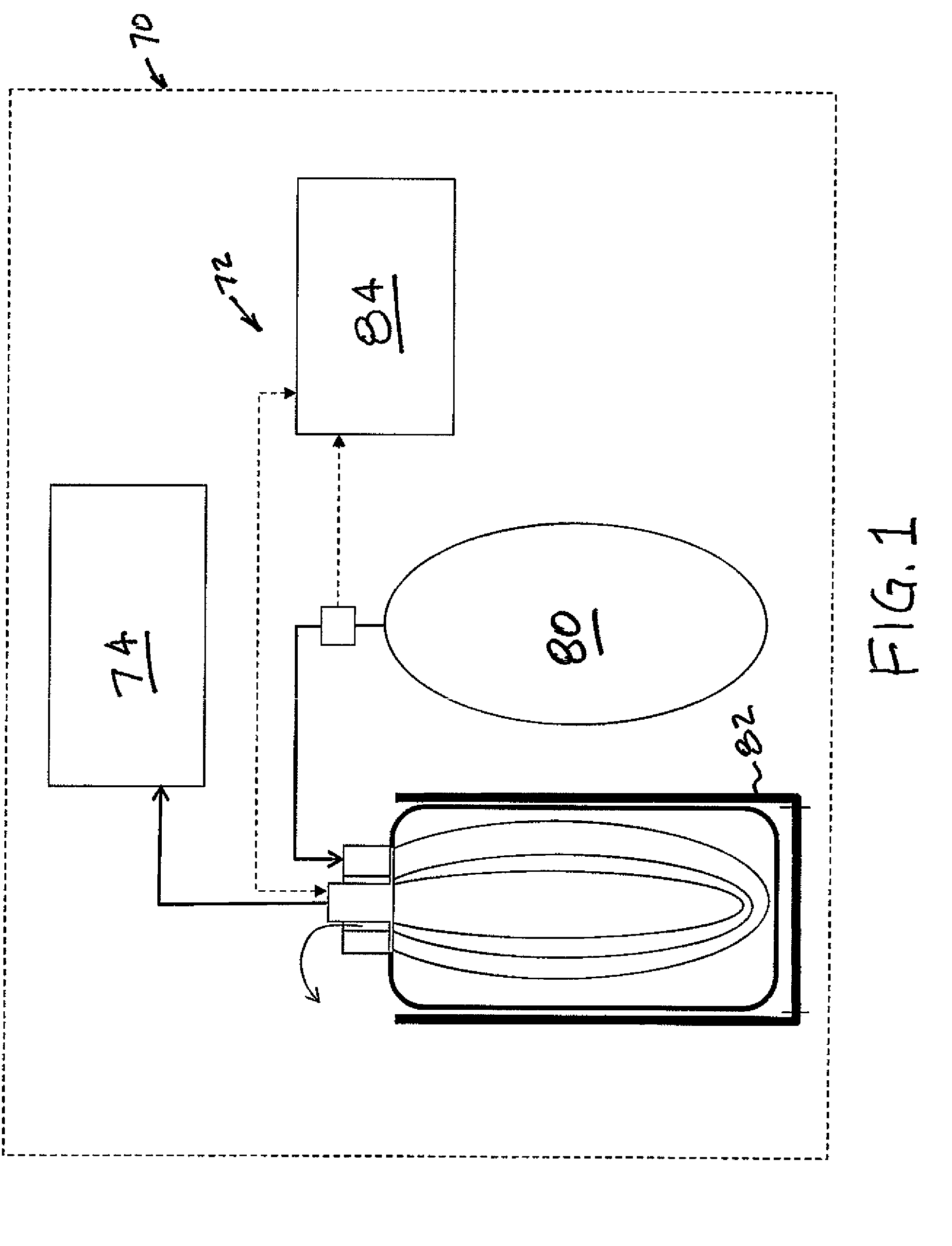
[0098]Referring to FIG. 1, a photolithography system 70 including a dispensing system 72 for supplying a lithographic processor 74 is depicted in an embodiment of the invention. The dispensing system 72 includes a pressure source 80 operatively coupled to a bag-in-bag-in-bottle device 100 that is disposed in a receiver 82. A process controller 84 may be operatively coupled to the dispensing system 72 for control and monitoring of the pressure source 80 and the bag-in-bag-in-bottle device 100.

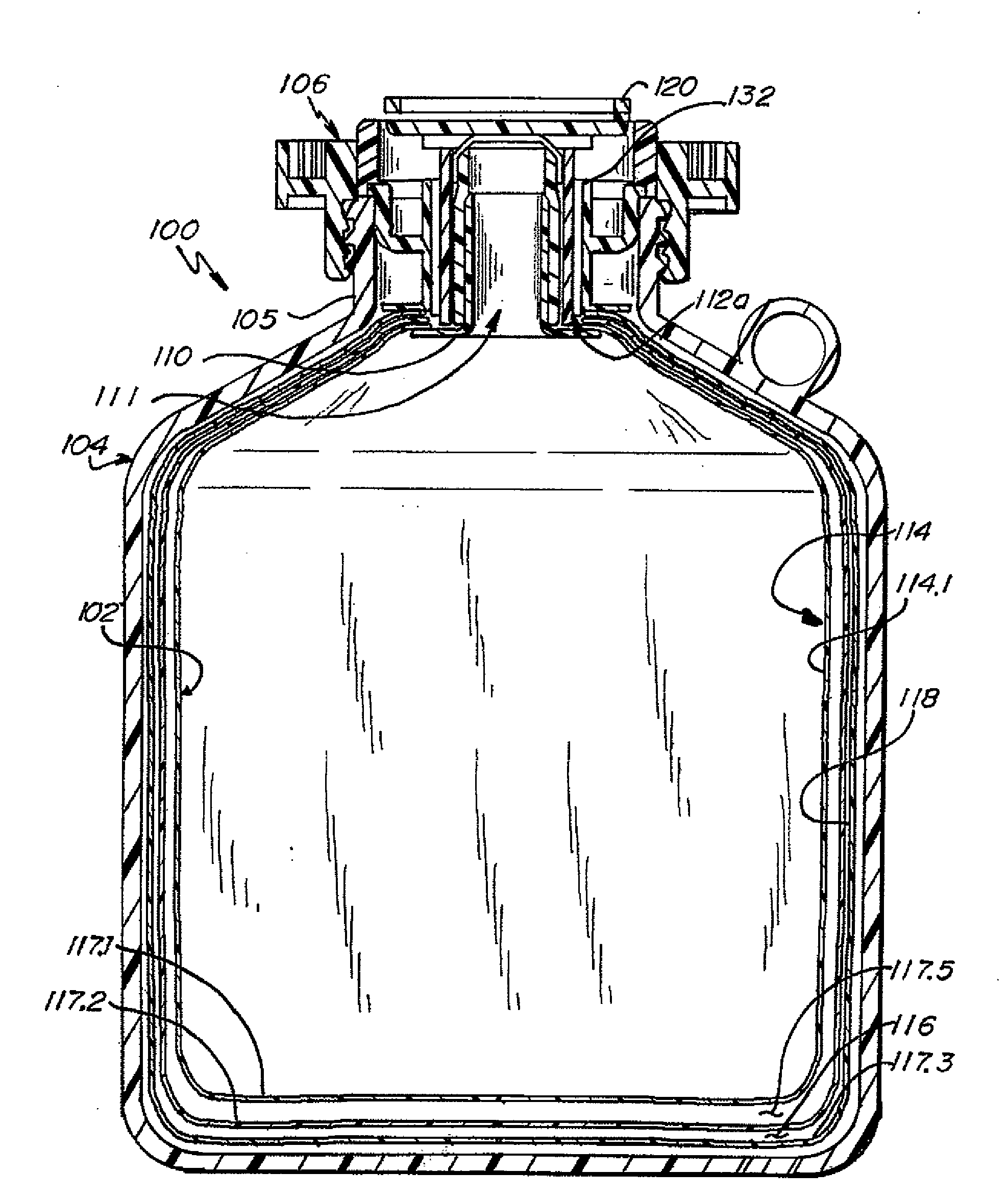
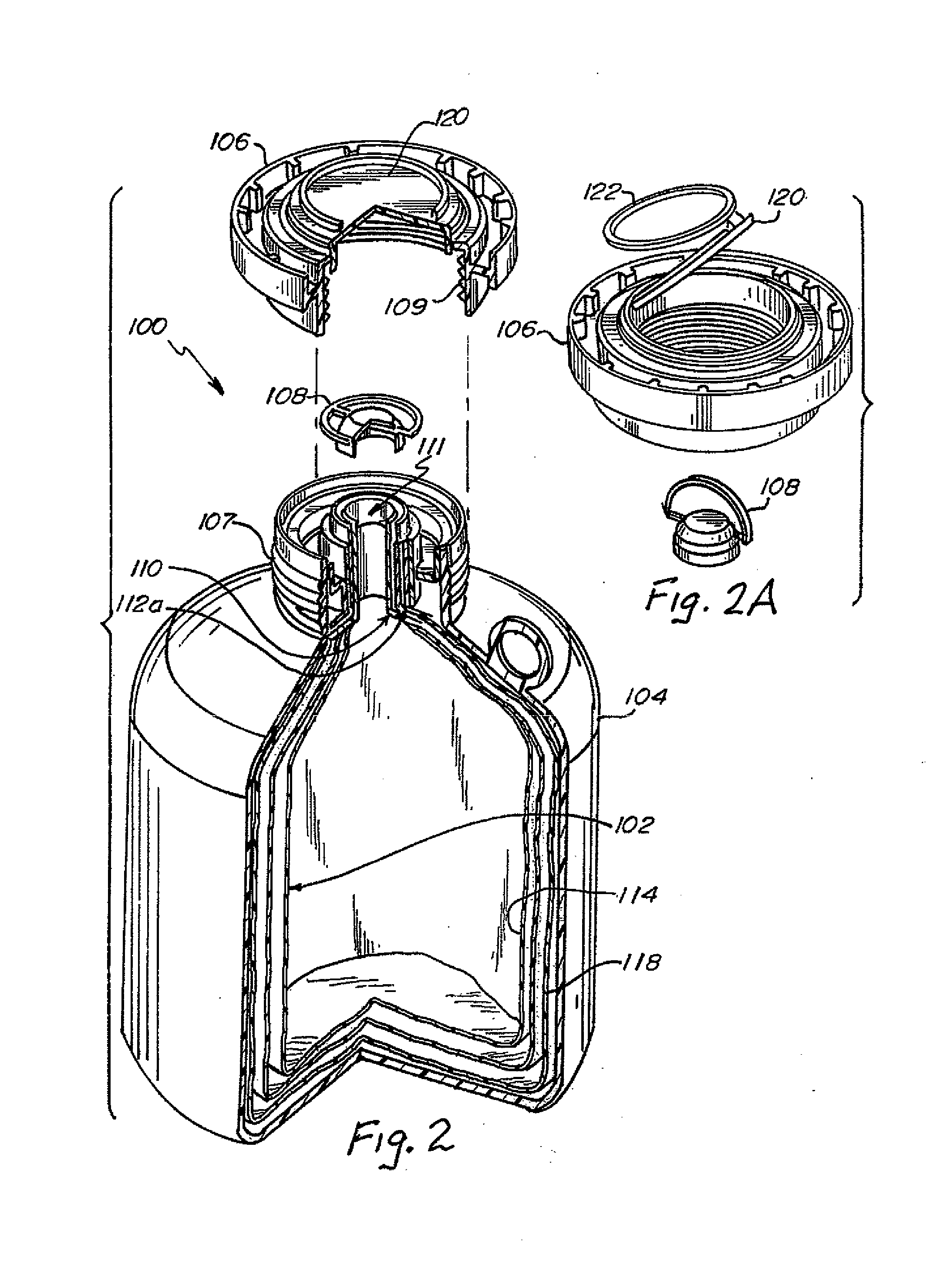
[0099]Referring to FIGS. 2, 2A and 2B, a representative embodiment of the bag-in-bag-in-bottle device 100 comprising a flexible bag-in-bag assembly 102, a containment vessel 104, and a cap assembly 106 is depicted in an embodiment of the invention. The bag-in-bag assembly 102 comprises an inner dispensing fitment110 nested inside an outer fitment 112a, and an inner flexible container 114 nested inside a dual-walled outer flexible container 118. The inner dispensing fitment 110 is joined to the i...


PUM

PropertyMeasurementUnit
Lengthaaaaaaaaaa
Forceaaaaaaaaaa
Flexibilityaaaaaaaaaa

Abstract

A bag-in-bag-in-bottle assembly formed by a flexible dispensing container with a dispensing fitment. The dispensing container is positioned adjacent or sandwiched between one or more flexible pressurization containers having a separate inlet / outlet path through a second fitment. The bag-in-bag assembly can then be placed in a containment vessel with the fitments mounted such that it is accessible on the vessel. A liquid can be extracted from the dispensing container by introducing a fluid into the pressurization container(s) with enough pressure to force the liquid out through the dispensing fitment. A contoured dispensing head may be coupled to the bag-in-bag-in-bottle assembly using a earn actuation arrangement for simultaneously locking the pressurization, vent and fluid extraction couplings.

Description

RELATED APPLICATIONS[0001]The present application claims the benefit of U.S. Provisional Application Nos. 60 / 968,510 filed Aug. 28, 2007, 60 / 992,292 filed Dec. 4, 2007, 61 / 025,547 filed Feb. 1, 2008, and 61 / 068,030 filed Mar. 4, 2008, all of which are hereby incorporated by reference herein in their entirety.FIELD OF THE INVENTION[0002]The present invention is generally directed to the field of flexible plastic materials for containment of liquids. More specifically, the present invention is directed to a method, apparatus, dispense systems, and components for dispensing a dispense fluid by providing pressurization fluid.BACKGROUND OF THE INVENTION[0003]The concept of collapsible containers held in rigid containers has been practiced for many years. These concepts can range from the relatively simple such as, a cardboard coffee tote with a flexible plastic bladder, to more complex systems for handling hazardous or highly pure chemicals in specialized double-wall sealed containers. R...

Claims


Application Information

Patent Timeline
IPC IPC(8): B67D5/42B65D35/14B23P11/00B65D35/28B65D35/56G01F11/00B67D7/60B67D7/02
CPCB65D83/0055Y10T29/49826B67D7/0255B67D2001/0828B67D1/0462
Inventor LEYS, JOHN A.HENNEN, JOHN M.JOHNSON, MICHAEL L.
Owner ENTEGRIS INC
Why Eureka
Try Eureka