Seat belt retractor

a seat belt and retractor technology, applied in the field of seat belt retractors, can solve the problems of increasing the inability to operate the webbing winding apparatus normally, and the increase in the manufacturing cost of the retractor, so as to reduce the weight of the seat belt retractor and simplify the manufacturing process.

Inactive Publication Date: 2009-03-05
AUTOLIV DEV AB
View PDF26 Cites 23 Cited by
  • Summary
  • Abstract
  • Description
  • Claims
  • Application Information

AI Technical Summary

Benefits of technology

[0074]An object of the present invention is to provide a seat belt retractor capable of

Problems solved by technology

Although the webbing winding apparatus has advantages in that uniform tension is applied to the frame connection part in the tension direction when the webbing belt is extracted and elastic deformation of the connection part is uniformized, since the flame is deformed due to the tension applied to the frame, the webbing winding apparatus cannot be normally operated.
Although the seat belt retractor has an advantage in that there is no assembly error since the torsion bar and the ratchet wheel are assembled at a predetermined angle, because both ends of the torsion bar have a polygonal shape it is difficult to manufacture the torsion bar, and thus manufacturing cost may increase.
Although the seat belt retractor has an advantage in that the wire absorbs distortion of the torsion bar, since a curved path should be formed at the winding drum, the manufacturing process is difficult and therefore manufacturing cost of the retractor is also increased.
As described above, the second protrusion formed at the clutc

Method used


Image

  • Seat belt retractor
  • Seat belt retractor
  • Seat belt retractor

Examples


first embodiment

[0300]As shown in FIGS. 28 and 29, a locking member coupling structure of the seat belt retractor in accordance with the present invention includes a leaf spring 725 fixed to a boss 721 of a locking clutch 720, and a fixing piece 731 projecting from a lock arm 730 to fix the leaf spring 725.

[0301]In this embodiment, a locking member 700 is installed at the seat belt retractor to allow a webbing to be smoothly released or rewound when the webbing is released with a normal speed, and prevent the webbing from being released or rewound when the webbing is rapidly released or rewound.

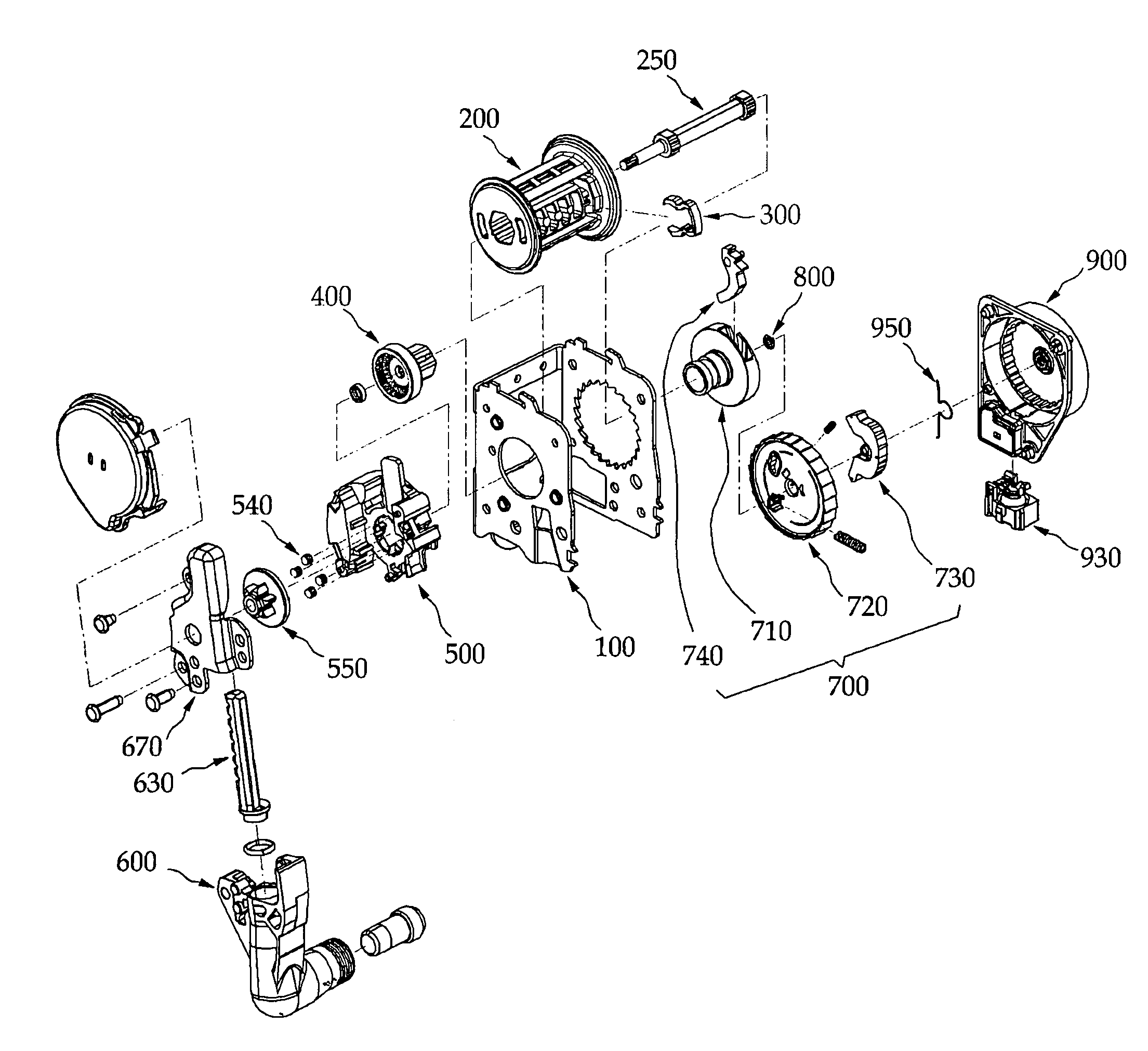
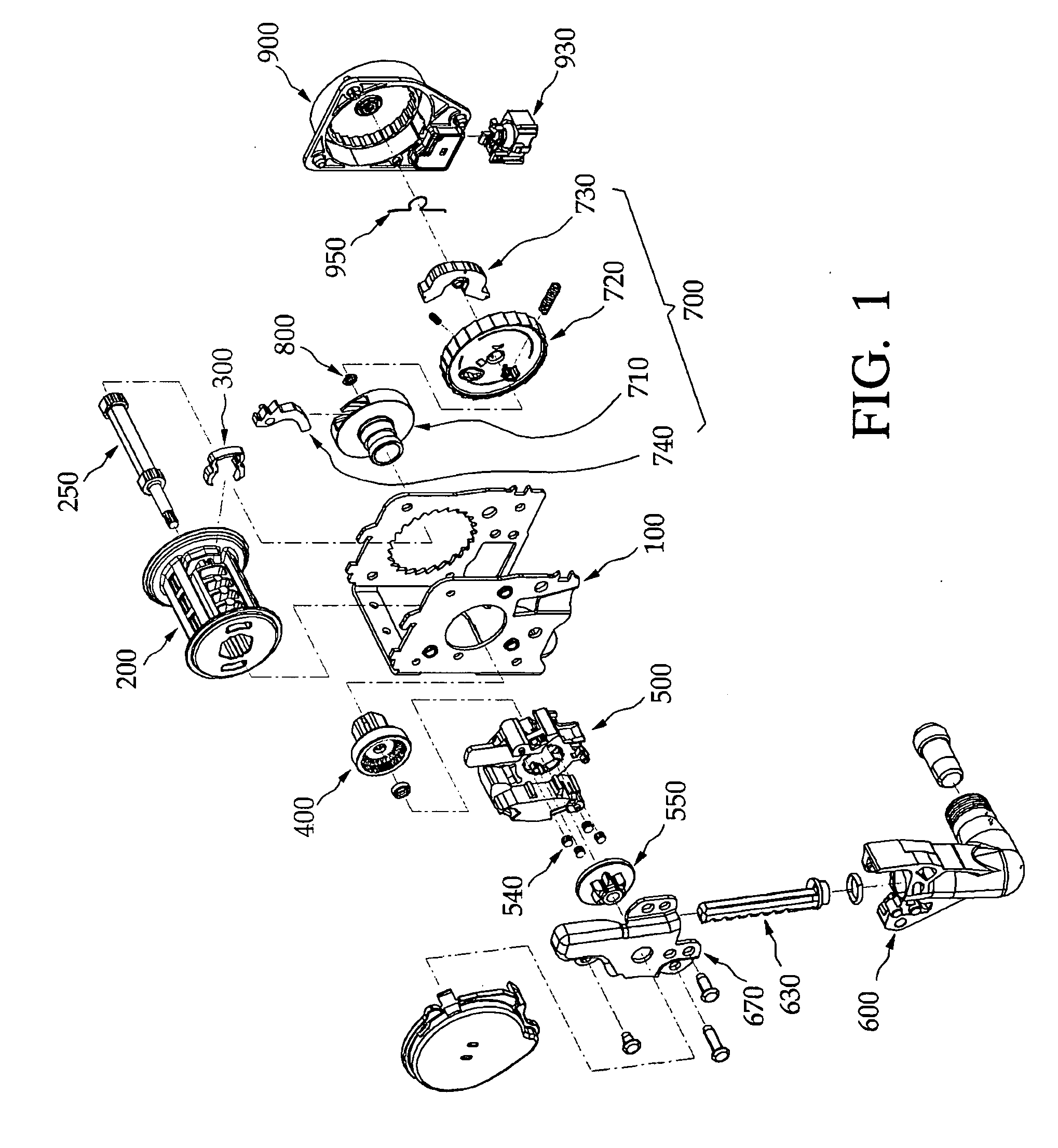
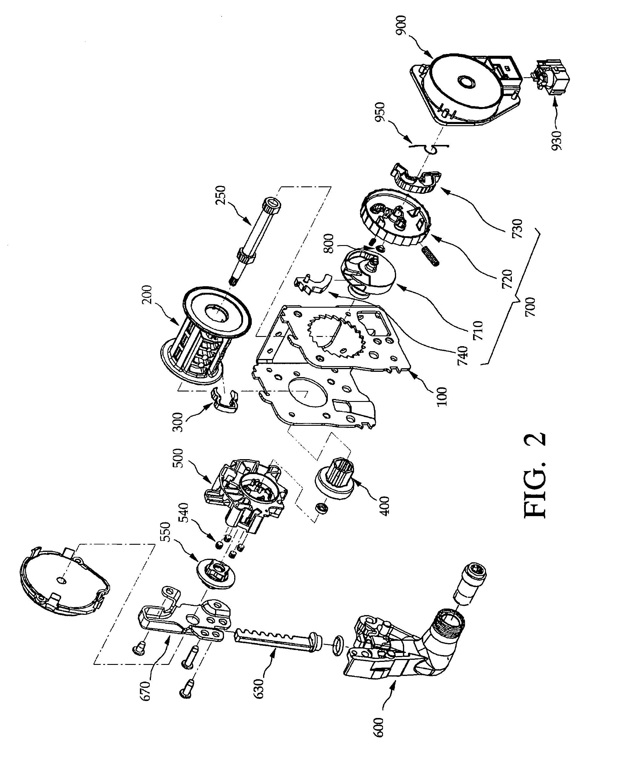
[0302]The locking member 700 includes a guide drum 200 rotatably installed at a housing 100 constituting a main body of the seat belt retractor, a locking base 710 fixed to one side of the guide drum 200, a locking clutch 720 rotatably engaged with one side of the locking base 710, and the lock arm 730 installed at one side of the locking clutch 720 to be pivoted to a limited angle.

[0303]As shown in FIGS. 28...

second embodiment

[0320]FIG. 30 is a side view of a locking member coupling structure of a seat belt retractor in accordance with a second exemplary embodiment of the present invention.

[0321]In this second embodiment, like reference numerals designate like components in the first embodiment, and descriptions thereof will be omitted.

[0322]In contrast to the first embodiment, one end of a leaf spring 725a of the second embodiment is fixed to a stopper 724 in the vicinity of a boss 721. That is, though one end of the leaf spring 725a of the first embodiment is fixed to the boss 721, one end of the leaf spring 725a of the second embodiment is fixed to the stopper 724, and the other end of the leaf spring 725a is fixed to a fixing piece 731 of a lock aim 730.

[0323]Since the leaf spring 725a of the second embodiment is fixed to a different position than the first embodiment and the locking clutch 720 and the lock arm 730 are operated in the same manner as the first embodiment, a description thereof will be...

third embodiment

[0324]A third embodiment of the present invention will be described with reference to FIG. 31.

[0325]As shown in FIG. 31, one end of a torsion spring 725b is in contact with one side of a lock arm 730. The torsion spring 725b extends in a rotation center direction of the lock arm 730 to be wound on a rotation center of the lock arm 730 at its intermediate portion in a circular or arcuate shape. The other end of the torsion spring 725b is fixed to one side of a stopper 724.

[0326]That is, the torsion spring 725b extends from both ends thereof to form a predetermined angle in a symmetrical manner with reference to a rotation center of the lock arm 730 such that one end is in contact with the lock arm 730 and the other end is fixed to the stopper 724.

[0327]The one end of the fixed torsion spring 725b is a free end such that the lock arm can be pivoted within a limited angular range, and the other end of the torsion spring 725b is an end securely fixed to the stopper 724.

[0328]Similar to ...


PUM


Abstract

Provided is a seat belt retractor capable of having its assembly readily performed to increase assembly efficiency, simplifying shapes of components to readily manufacture the retractor and reduce manufacturing cost, and preventing a webbing from being hooked when the webbing is rewound. The seat belt retractor includes a housing constituting a main body of the seat belt retractor, a guide drum rotatably installed in the housing, a connector inserted into one side of the guide drum, a base member surrounding the connector, a gear member inserted into the base member, a cylinder for operating the gear member, a torsion bar inserted into the guide drum, a locking member fixedly inserted between the torsion bar and the guide drum, a locking clutch installed at one surface of the locking member, a mechanism cover installed at one surface of the locking clutch, and a friction spring installed in the mechanism cover to stop operation of a lock arm fixed to the locking clutch.
Therefore, an operator can assemble the base member and the gear member while viewing them. In addition, the clutch rollers rotate while moving outwardly along the slant surfaces of the slant gear to rotate the connector and rewind the webbing. Thus, shock applied to a passenger is lessened.

Description

CROSS-REFERENCE TO RELATED APPLICATION[0001]This application claims the benefit of Korean Patent Application No. 2007-0048823, filed May 18, 2007, the disclosure of which is hereby incorporated herein by reference in its entirety.BACKGROUND OF THE INVENTION[0002]1. Field of the Invention[0003]The present invention relates to a seat belt retractor, and more particularly, to a seat belt retractor capable of adhering a driver and a passenger to their seats by backwardly rotating a seat belt operating on vehicle collision.[0004]2. Description of the Prior Art[0005]A seat belt or an airbag is installed in a vehicle to safely protect a driver and a passenger from traffic accidents.[0006]Such a seat belt is a basic safety device installed to operate upon vehicle accidents such as front collision, side collision, roll, and so on, to thereby maximally protect a driver and a passenger.[0007]A widely used seat belt is a thepoint safety belt constituted of a waist belt for protecting the waist ...

Claims


Application Information

Patent Timeline
IPC IPC(8): B60R22/34B65H75/48
CPCB60R22/3413B60R22/405B60R2022/468B60R2022/287B60R22/4633B60R22/46B60R22/36B60R22/34
Inventor CHOI, IN-SULEELEE, BYUNG-JINLEE, DONG-SUBBAI, SANG-HONGBAE, GI-YOUNGKIM, JONG-KAGKIM, DO-SHIK
Owner AUTOLIV DEV AB
Why Eureka
Try Eureka