

Auxiliary electric power supply for vehicle and charger/discharger for vehicle
- Summary
- Abstract
- Description
- Claims
- Application Information
AI Technical Summary
Benefits of technology
Problems solved by technology
Method used
Image

Examples
first exemplary embodiment
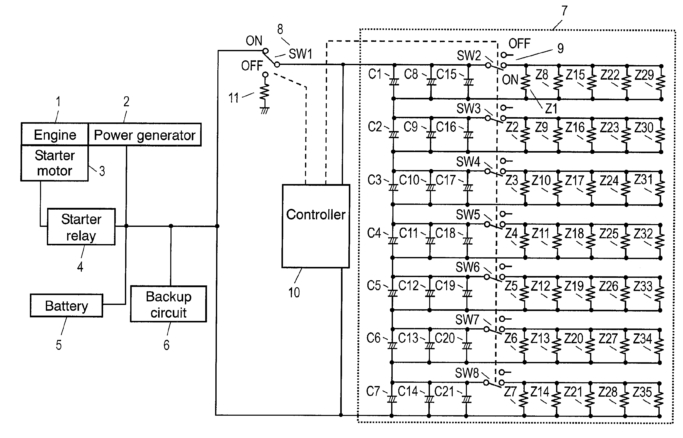
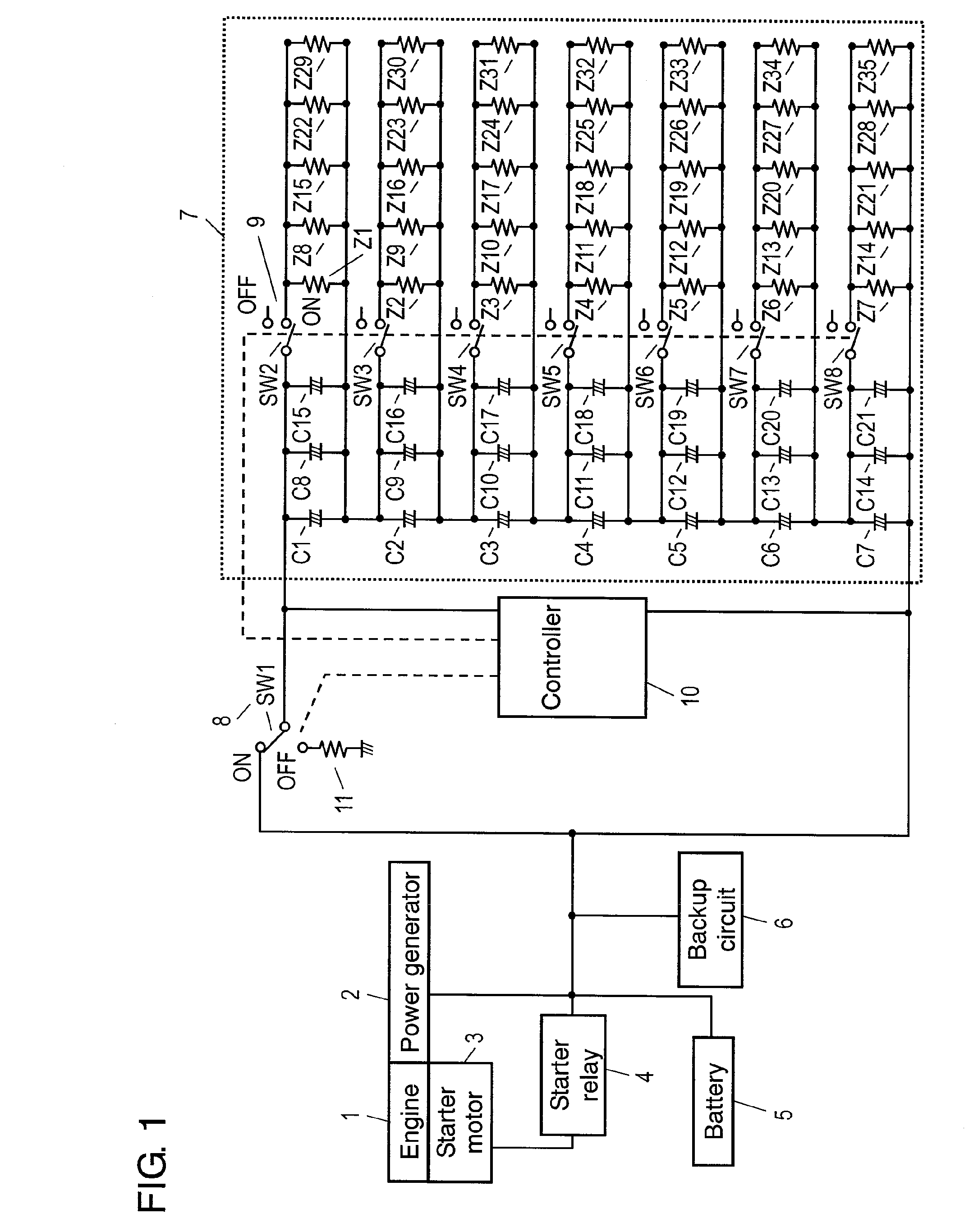
[0015]FIG. 1 is a block diagram illustrating makeup of a charger / discharger for a vehicle, according to the first exemplary embodiment of the present invention, in conjunction with a circuit diagram. The charger / discharger according to the present embodiment has power generator 2, battery 5, and an auxiliary electric power supply for a vehicle including capacitor bank 7, first switch 8, and controller 10.
[0016]Power generator 2 is driven in conjunction with engine 1. Starter motor 3 starts engine 1. Battery 5 generally formed of a lead storage battery supplies starter motor 3 with power through starter relay 4. Backup circuit 6 supplies starter motor 3 with backup energy in an emergency through starter relay 4. Capacitor bank 7 is formed of electric double layer capacitors interlinked.
[0017]First switch 8 is electrically connected to the I / O end of capacitor bank 7. Capacitor bank 7 is connected to power generator 2, starter relay 4, battery 5, and backup circuit 6 through first swi...
second exemplary embodiment
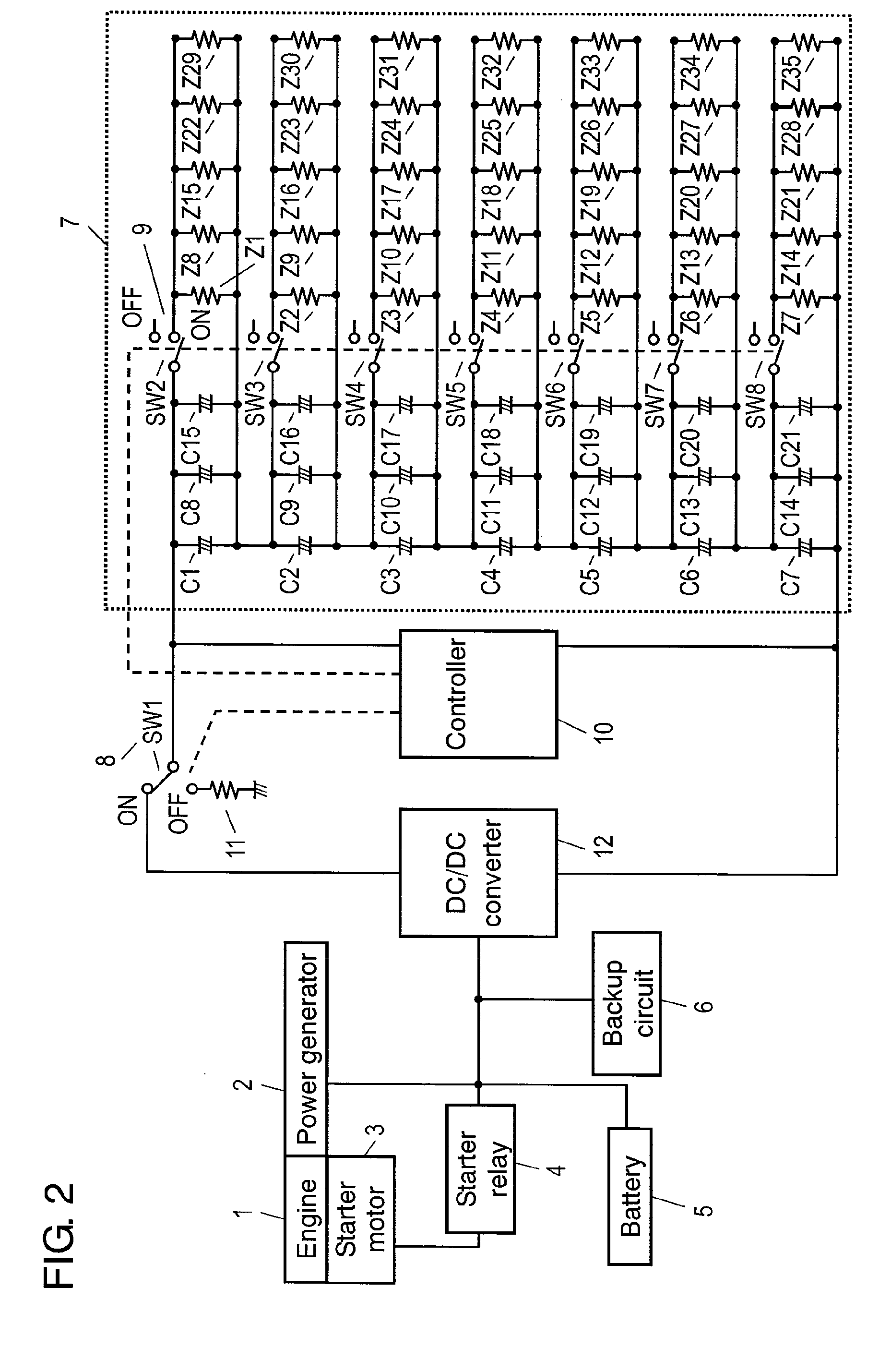
[0043]FIG. 2 is a block diagram illustrating makeup of a charger / discharger for a vehicle according to the second exemplary embodiment of the present invention, in conjunction with a circuit diagram. The present embodiment is different from the first one in that DC / DC converter 12 is provided between starter relay 4 and switch 8. That is, DC / DC converter 12 is provided between the I / O end of capacitor bank 7 and first switch 8, to raise the output voltage. The basic composition otherwise is the same as that in FIG. 1, and thus a same reference mark is given to what has the same makeup as that of the first embodiment, to omit detailed descriptions.
[0044]The power generated by generator 2 driven in conjunction with the rotation of engine 1 is charged in battery 5, as well as in capacitor bank 7 through DC / DC converter 12. When driving starter motor 3 uses the power accumulated in capacitor bank 7, the power from the electric double layer capacitors can be supplied with the voltage rai...
PUM
 Abstract
Description
Claims
Application Information