Inspection apparatus and inspection method

Active Publication Date: 2009-03-05
TOKYO ELECTRON LTD
View PDF0 Cites 12 Cited by
  • Summary
  • Abstract
  • Description
  • Claims
  • Application Information

AI Technical Summary

Benefits of technology

[0020]In accordance with the present invention, it is possible to provide an inspection apparatus and an inspection method capable of shortening an inspection time by inspecting a target object without preliminarily heating or co

Problems solved by technology

Thus, there exists a great temperature difference between the wafer and the probe card.
Therefore, the device and the probes make contact with each other under a load greater than the predetermined contact load, which may possibly cause damage to the device or the probes.
As the probe card becomes greater in size, however, it takes

Method used


Image

  • Inspection apparatus and inspection method
  • Inspection apparatus and inspection method
  • Inspection apparatus and inspection method

Examples


Embodiment Construction

[0025]Hereinafter, an embodiment of the present invention will be described with reference FIGS. 1 to 3.

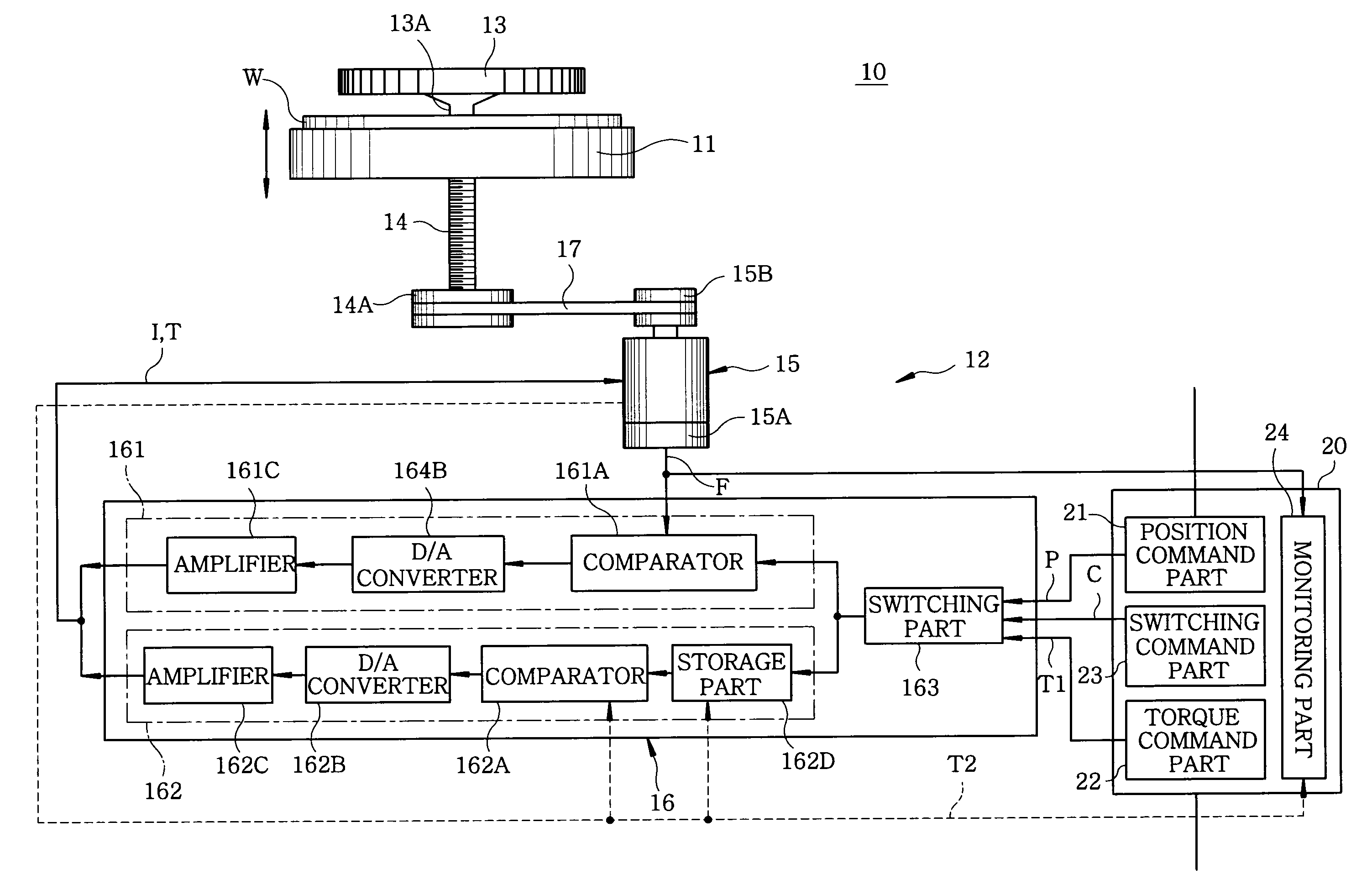
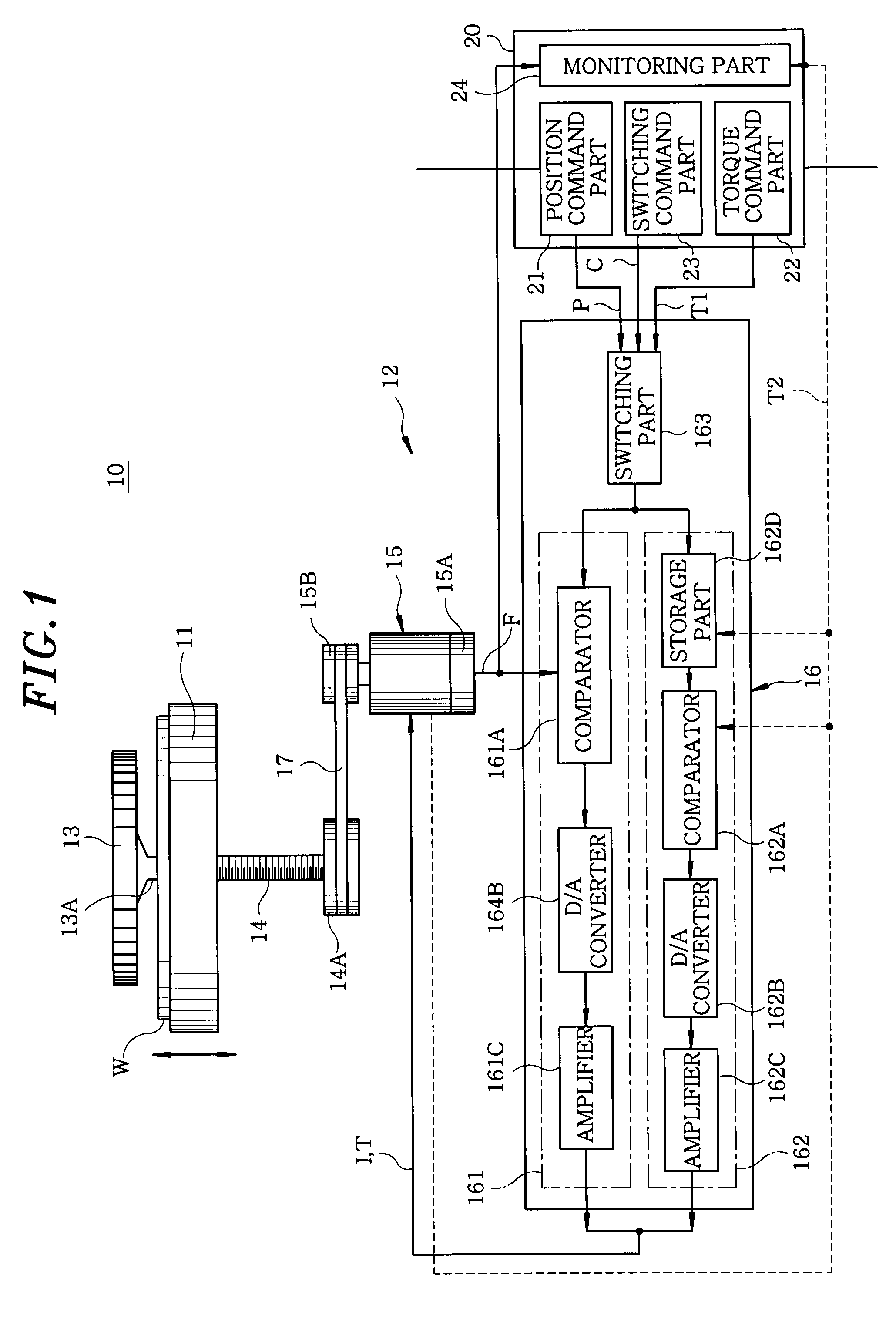
[0026]First, an inspection apparatus of the present embodiment will be described with reference to FIG. 1. As shown in FIG. 1, the inspection apparatus 10 of the present embodiment includes, e.g., a mounting table 11 for mounting thereon a target object (e.g., a wafer) W, the mounting table 11 having therein a temperature controller, a vertical drive mechanism 12 for raising and lowering the mounting table 11, an XY table (not shown) on which the mounting table 11 and the vertical drive mechanism 12 are arranged, a probe card 13 arranged above the mounting table 11 and provided with a plurality of probes 13A and an alignment mechanism (not shown) for aligning the wafer W mounted on the mounting table 11 with the probes 13A of the probe card 13. In a high temperature inspection for example, the vertical drive mechanism 12 is designed to change the current position of the mounting t...


PUM


Abstract

An inspection apparatus for inspecting electric characteristics of a plurality of devices formed on a target object includes a vertical drive mechanism for lifting and lowering a movable mounting table and a control unit for controlling the vertical drive mechanism. The vertical drive mechanism includes an elevation shaft connected to the mounting table and a servo motor for driving the elevation shaft to lift and lower the mounting table. Further, the control unit has a servo driver which includes a position control part for controlling a position of the servo motor, a torque control part for controlling a torque of the servo motor as a probe card is expanded or contracted by a change in temperature and a switching part for switching the position control part and the torque control part.

Description

FIELD OF THE INVENTION[0001]The present invention relates to an inspection apparatus and an inspection method; and, more particularly, to an inspection apparatus and an inspection method capable of shortening an inspection time.BACKGROUND OF THE INVENTION[0002]A conventional inspection apparatus includes, e.g., a mounting table for mounting thereon a target object (e.g., a wafer) to be inspected, the mounting table having therein a temperature controller for controlling the temperature of the wafer, a vertical drive mechanism for moving the mounting table up and down, an XY table for moving the mounting table and the vertical drive mechanism in X and Y directions, a probe card arranged above the mounting table, and an alignment mechanism for accurately aligning a plurality of probes of the probe card with a plurality of electrode pads of the target object placed on the mounting table. The temperature of the wafer placed on the mounting table is controlled to a predetermined value by...

Claims


Application Information

Patent Timeline
IPC IPC(8): G01R1/073
CPCG01R31/2891G01R1/073H01L22/00
Inventor YAMAMOTO, YASUHITOINOMATA, ISAMU
Owner TOKYO ELECTRON LTD
Why Eureka
Try Eureka