Apparatus and method of driving data of liquid crystal display device

Inactive Publication Date: 2009-03-05
LG DISPLAY CO LTD
View PDF19 Cites 29 Cited by
  • Summary
  • Abstract
  • Description
  • Claims
  • Application Information

AI Technical Summary

Benefits of technology

[0012]The delay circuit includes a plurality of RC delaying parts connected to a supply line of the reference source output enable signal in series. Also, the plurality of RC delaying parts are provided with time constants set with the same value. The delay time of rising and falling times in the plurality of source output enable signals is increased in proportion to the number of RC delaying parts thr

Problems solved by technology

Due to the high peak current of the data driver, the related art liquid crystal display device has a problem of electromagnetic interference EMI noise.
Also, the high peak curre

Method used


Image

  • Apparatus and method of driving data of liquid crystal display device
  • Apparatus and method of driving data of liquid crystal display device
  • Apparatus and method of driving data of liquid crystal display device

Examples


first embodiment

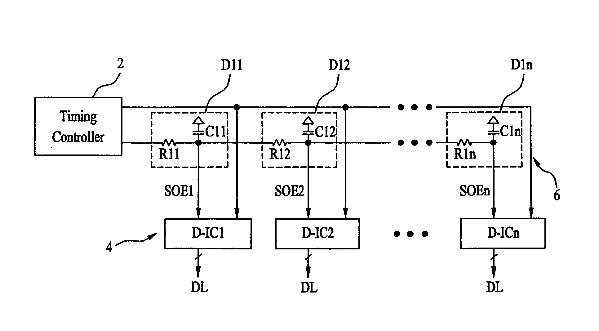
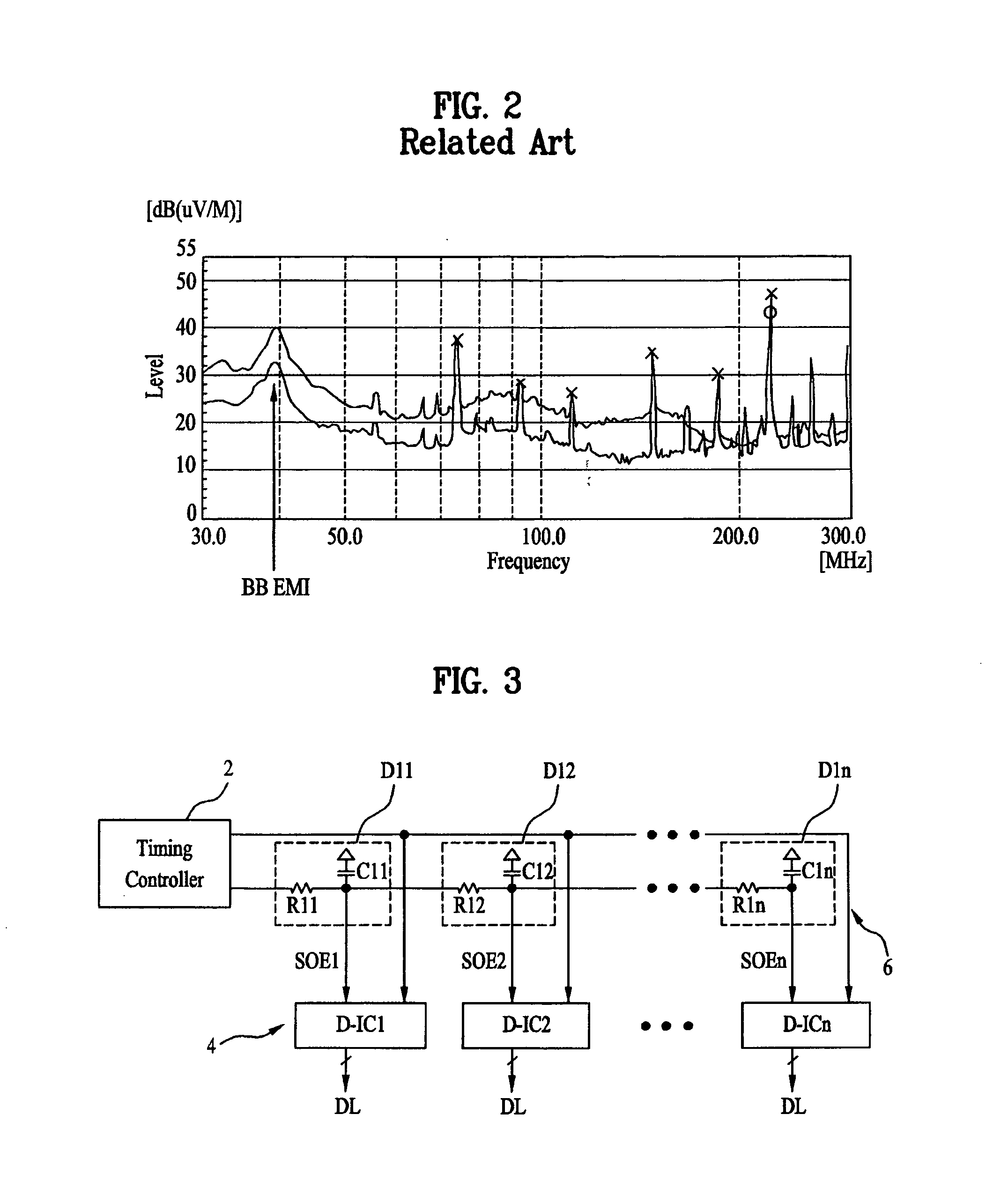
[0029]FIG. 3 is a block diagram schematically illustrating a data driving apparatus of a liquid crystal display device according to the present disclosure.

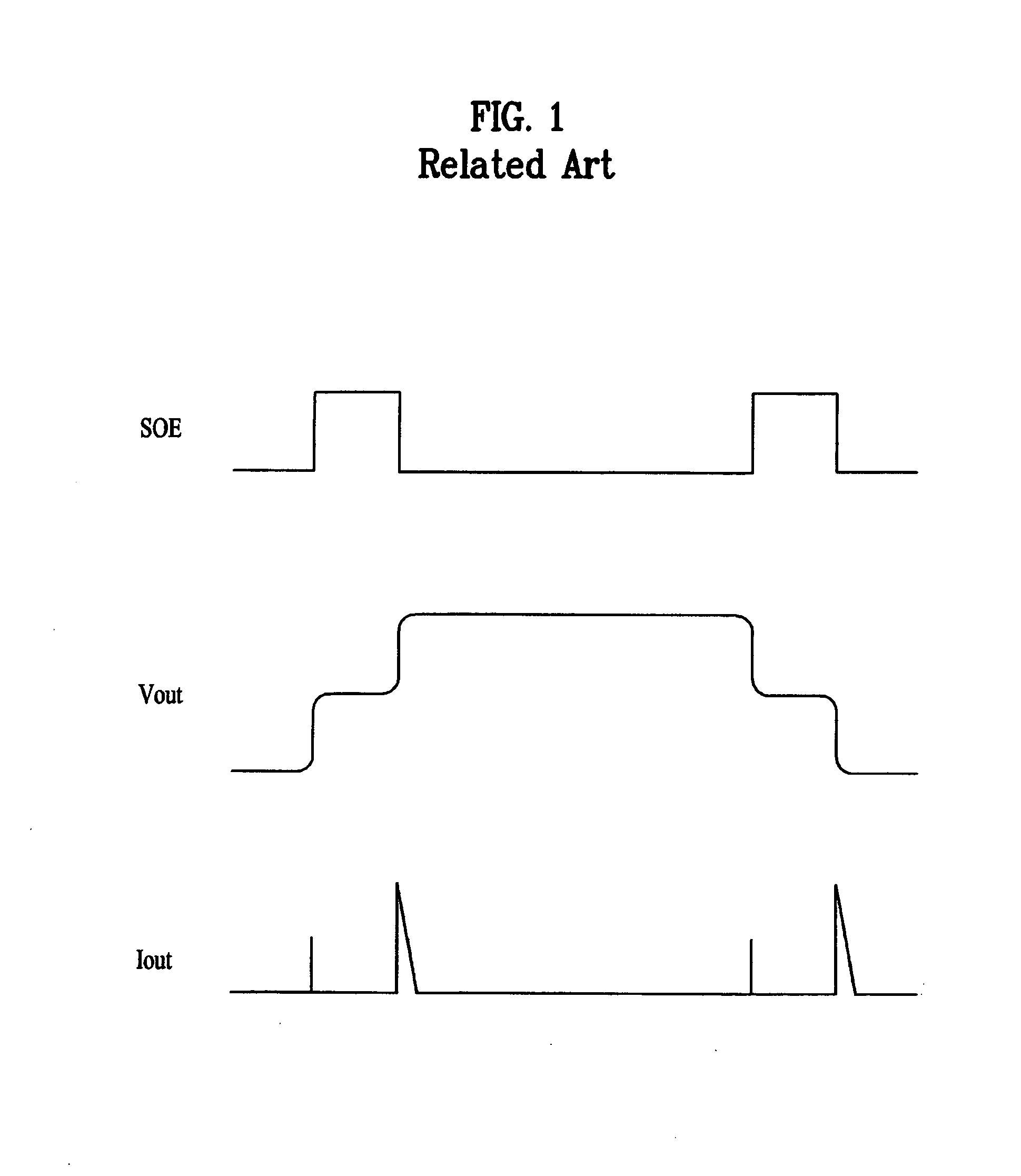
[0030]FIG. 4 is a driving waveform diagram of a data driving apparatus shown in FIG. 3.

[0031]As shown in FIG. 3, the data driving apparatus of liquid crystal display device is comprised of a timing controller 2 for supplying video data and control signals including SOE signals; a data driver 4 including a plurality of data integrated circuits (hereinafter, referred to as “IC”) D-IC1˜D-ICn to drive data lines DL of a liquid crystal panel under control of the timing controller 2; and a delay circuit 6 for delaying the SOE signal supplied from the timing controller 2 with different delay time periods, and supplying the SOE signal delayed with the different delay time periods to the plurality of data ICs D-IC1˜D-ICn, respectively. FIG. 4 illustrates an output voltage Vout and an output current Iout in the data driver 4 of FIG. 3, the ...

second embodiment

[0041]FIG. 5 is a block diagram schematically illustrating a data driving apparatus of a liquid crystal display device according to the present disclosure. The data driving apparatus of FIG. 5 is identical in structure to the data driving apparatus of FIG. 3 except that a delay circuit 8 is comprised of a plurality of delaying parts D21˜D2n connected to an SOE signal line in parallel, whereby the detailed explanation for the same parts will be omitted.

[0042]The delay circuit 8 shown in FIG. 5 includes the plurality of delaying parts D21˜D2n connected to the main SOE signal line in parallel, wherein the plurality of delaying parts D21˜D2n are provided with time constants R21C21˜R2nC2n set differently. If the time constants are differently set in the respective delaying parts D21˜D2n, each of the respective delaying parts D21˜D2n is provided with R and C components, wherein R and C components may be set differently in the respective delaying parts D21˜D2n, or any one of the R and C co...

third embodiment

[0047]FIG. 6 is a block diagram schematically illustrating a data driving apparatus of a liquid crystal display device according to the present disclosure.

[0048]The data driving apparatus shown in FIG. 6 is comprised of a timing controller 10 which supplies SOE signals; a first data driver 32 which includes a plurality of data ICs D-IC1˜D-IC4 connected through the timing controller 10 and a first PCB 22; a second data driver 34 which includes a plurality of data ICs D-IC5˜D-IC8 connected through the timing controller 10 and a second PCB 24; a first delay circuit 42 which is formed in the first PCB 22, wherein the first delay circuit 42 divides an SOE signal output from the timing controller 10 into SOE1 to SOE4 signals provided with the different delay times, and supplies the SOE1 to SOE4 signals to the data ICs D-IC1˜D-IC4; and a second delay circuit 44 which is formed in the second PCB 24, wherein the second delay circuit 44 divides the SOE signal output from the timing controller...


PUM


Abstract

An apparatus and method of driving data of a liquid crystal display device is disclosed, which can minimize an electromagnetic interference EMI noise by decreasing an output peak current of a data driver, the apparatus comprising a timing controller for supplying a reference source output enable signal; a delay circuit for delaying the reference source output enable signal and supplying a plurality of source output enable signals provided with the different delay times; and a data driver, including a plurality of data ICs to divide and drive data lines of a liquid crystal panel into a plurality of data blocks, for dispersing data output timing of the plurality of data ICs in response to the plurality of source output enable signals.

Description

CLAIM FOR PRIORITY[0001]This application claims the benefit of Korean Patent Application No. 2007-86988 filed Aug. 29, 2007, which is hereby incorporated by reference as if fully set forth herein.BACKGROUND OF THE INVENTION[0002]1. Field of the Invention[0003]The present invention relates to a liquid crystal display device, and more particularly, to an apparatus and method of driving data of a liquid crystal display device which can minimize an electromagnetic interference EMI noise by decreasing an output peak current of a data driver.[0004]2. Discussion of the Related Art[0005]Generally, a liquid crystal display device displays images by using the electric and optical properties of liquid crystal. The liquid crystal has the anisotropic property, whereby the liquid crystal is provided with refractive and dielectric indexes changed in long and short axes of liquid crystal molecules. In this respect, alignment of the liquid crystal molecules and the optical property of liquid crystal...

Claims


Application Information

Patent Timeline
IPC IPC(8): G09G3/36
CPCG09G3/3611G09G2370/08G09G2330/06G09G2300/0426G02F1/133G09G3/20G09G3/36
Inventor HA, SUNG CHULCHO, CHANG HUNHONG, JIN CHEOL
Owner LG DISPLAY CO LTD
Why Eureka
Try Eureka