Method Of Controlling A Direct-Injection Gaseous-Fuelled Internal Combustion Engine System With A Selective Catalytic Reduction Converter

Active Publication Date: 2013-01-24
WESTPORT FUEL SYST CANADA INC
View PDF9 Cites 15 Cited by
  • Summary
  • Abstract
  • Description
  • Claims
  • Application Information

AI Technical Summary

Benefits of technology

[0018]In preferred embodiments, for example for a 15 liter direct-injection natural gas internal combustion engine ignited by a diesel fuel, the delay in timing for injecting the gaseous fuel, measured in degrees of crank angle rotation can be between 14 and 25 degrees after top dead center. In such embodiments the controller can end injection of the first quantity of fuel at a timing when the crankshaft angle of rotation is within 1 degree b

Problems solved by technology

However, under the same temperature and pressure conditions generated by the compression of the charge within the combustion chamber, gaseous fuels such as natural gas will not reliably auto-ignite.
However, the applicants have found that combining an SCR converter with a gaseous-fuelled engine did not always achieve the same NOx conversion rates.
For conventional diesel engines there are many known approaches for increasing the exhaust gas temperature, but there are particular charact

Method used


Image

  • Method Of Controlling A Direct-Injection Gaseous-Fuelled Internal Combustion Engine System With A Selective Catalytic Reduction Converter
  • Method Of Controlling A Direct-Injection Gaseous-Fuelled Internal Combustion Engine System With A Selective Catalytic Reduction Converter
  • Method Of Controlling A Direct-Injection Gaseous-Fuelled Internal Combustion Engine System With A Selective Catalytic Reduction Converter

Examples


Example

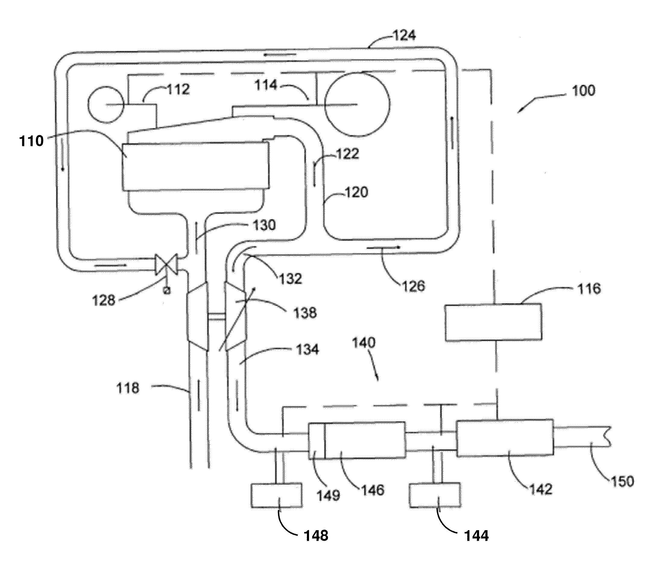
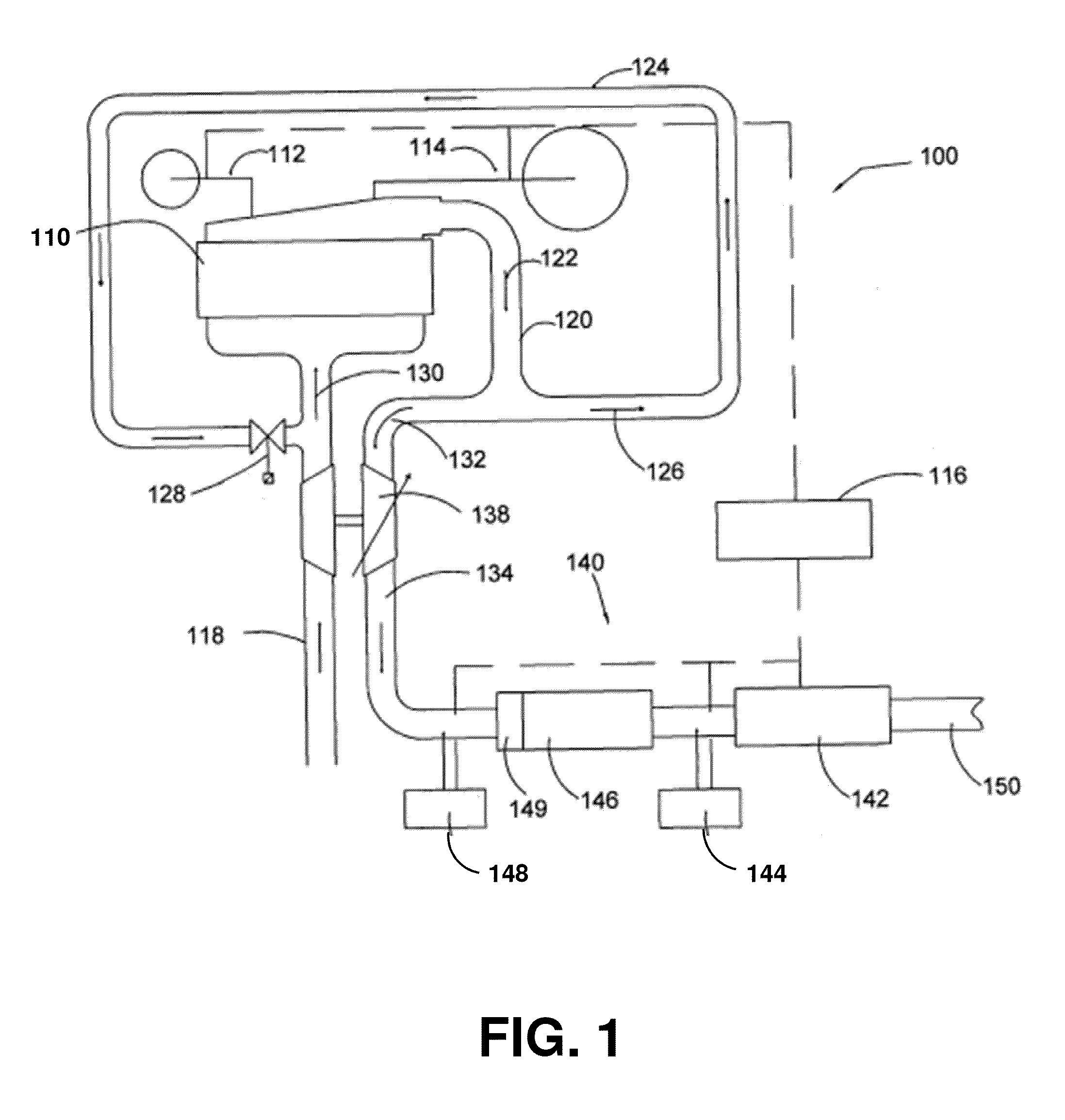
[0029]FIG. 1 shows a schematic view of a direct-injection gaseous-fuelled internal combustion engine system comprising an exhaust after-treatment subsystem and an exhaust gas recirculation loop. Herein “direct-injection” is used to refer to the injection of fuel directly into the combustion chamber of an internal combustion engine, which is an approach that is technically distinct from engines that inject fuel into an engine's intake manifold or into the intake ports on the manifold side of the engine's intake valves. With direct-injection engines the fuel can be injected later in the engine cycle, thereby avoiding fuelling and compression ratio limitations associated with avoiding engine knock (“pre-mature detonation of the fuel”). Conversely, this generally allows direct-injection engines to employ higher compression ratios, and achieve higher efficiencies and power outputs compared to other engines with the same displacement. The disclosed method can be used with engines that inj...


PUM


Abstract

A method controls a direct-injection gaseous-fuelled internal combustion engine system to improve the conversion efficiency of an SCR converter that is operative to reduce levels of NOx. The method comprises detecting when the internal combustion engine is idling and timing the injection of a first quantity of fuel to begin injection when the engine's piston is near top dead center; and controlling the temperature of exhaust gas to be above a predetermined temperature that is defined by an operating temperature range that achieves a desired conversion efficiency for the selective catalytic reduction converter, by: (a) timing injection of the gaseous fuel to begin after timing for injection the first quantity of fuel, and (b) increasing exhaust gas temperature by increasing a delay in timing for injecting the gaseous fuel, while limiting the delay to keep concentration of unburned fuel exiting the combustion chamber below a predetermined concentration.

Description

CROSS-REFERENCE TO RELATED APPLICATION(S)[0001]This application is a continuation of International Application No. PCT / CA2011 / 000442, having an international filing date of Apr. 15, 2011, entitled “Method Of Controlling A Direct-Injection Gaseous-Fuelled Internal Combustion Engine System With A Selective Catalytic Reduction Converter”. The '442 international application claimed priority benefits, in turn, from Canadian Patent Application No. 2,698,342 filed on Apr. 20, 2010, and from Canadian Patent Application No. 2,702,246 filed on May 7, 2010, each of which is hereby incorporated by reference herein in its entirety.FIELD OF THE INVENTION[0002]The present invention relates to a method of controlling a direct-injection gaseous-fuelled internal combustion engine system with a selective catalytic reduction converter to reduce emissions of NOx when the engine is idling.BACKGROUND OF THE INVENTION[0003]Presently, most over-the-road heavy vehicles are fuelled by gasoline or diesel fuel....

Claims


Application Information

Patent Timeline
IPC IPC(8): F01N3/18F02M26/05
CPCF01N3/106F01N13/009F01N2430/08F01N2900/08F01N2900/1404F01N2900/1621F02B37/00F02D19/10F02D41/0027F02D41/0245F02D41/0275F02M25/0707Y02T10/36Y02T10/44Y02T10/26Y02T10/32F02D19/061F02D19/0689F02D19/081F02M21/0275F02D19/024Y02T10/24F02D41/08F02D41/1446F02D41/402F02D41/403F02D41/0025F02D2041/389F01N13/0097F01N3/208F02M26/05Y02T10/12Y02T10/30Y02T10/40
Inventor RICHARDSON, SEAN D.LEBASTARD, OLIVER P.M.
Owner WESTPORT FUEL SYST CANADA INC
Why Eureka
Try Eureka