
Implantable Systemic Blood Pressure Measurement Systems and Methods

a technology of blood pressure measurement and implantable system, which is applied in the direction of catheters, angiography, therapy, etc., can solve the problems of slow approach, inability to provide timely readings, and requires the intervention of a skilled clinician, so as to remove respiratory affects and maximize the signal-to-noise ratio

Active Publication Date: 2009-03-05
PACESETTER INC
View PDF30 Cites 67 Cited by
  • Summary
  • Abstract
  • Description
  • Claims
  • Application Information

AI Technical Summary

Benefits of technology

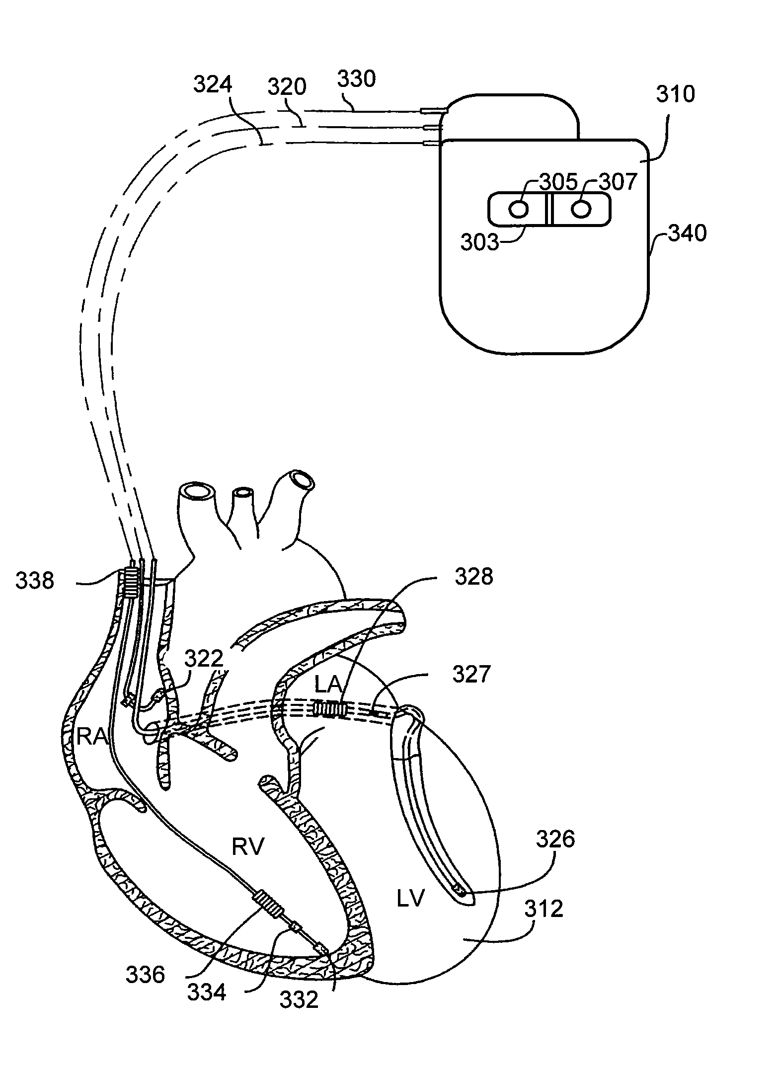
[0076]Where the PPG sensor is incorporated into or attached to a chronically implantable device 310, the light source 305 and the light detector 307 can be mounted adjacent to one another on the housing or header of the implantable device. The light source 305 and the light detector 307 are preferably placed on the side of the implantable device 310 that, following implantation, faces the chest wall, and are configured such that light cannot pass directly from the source to the detector. The placement on the side of the device 310 that faces the chest wall maximizes the signal to noise ratio by directing the signal toward the highly vascularized musculature, and shielding the source and detector from ambient light that enters the body through the skin. Alternatively, at the risk of increasing susceptibility to ambient light, the light source 305 and the light detector 307 can be placed on the face of the device 310 that faces the skin of the patient.
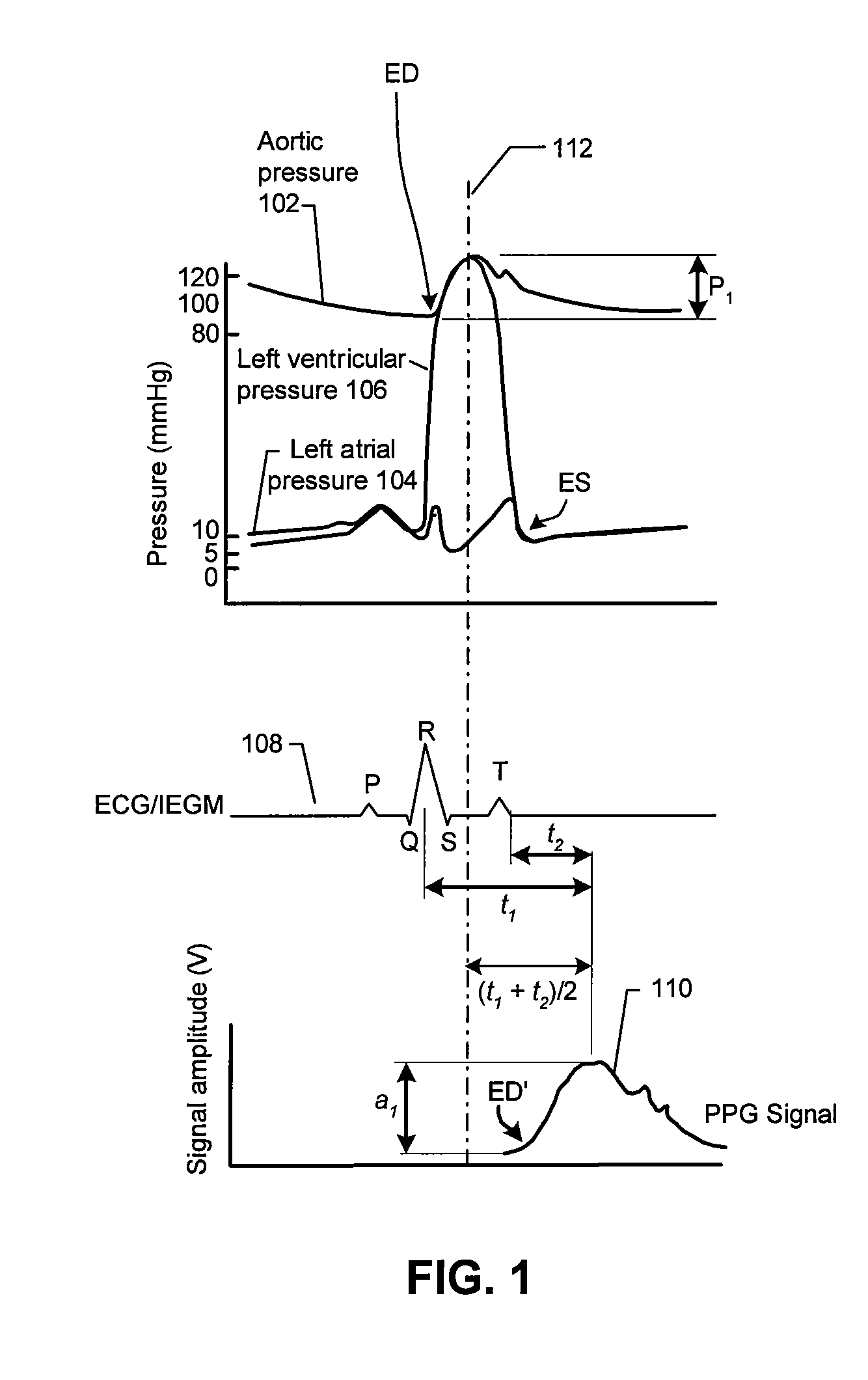
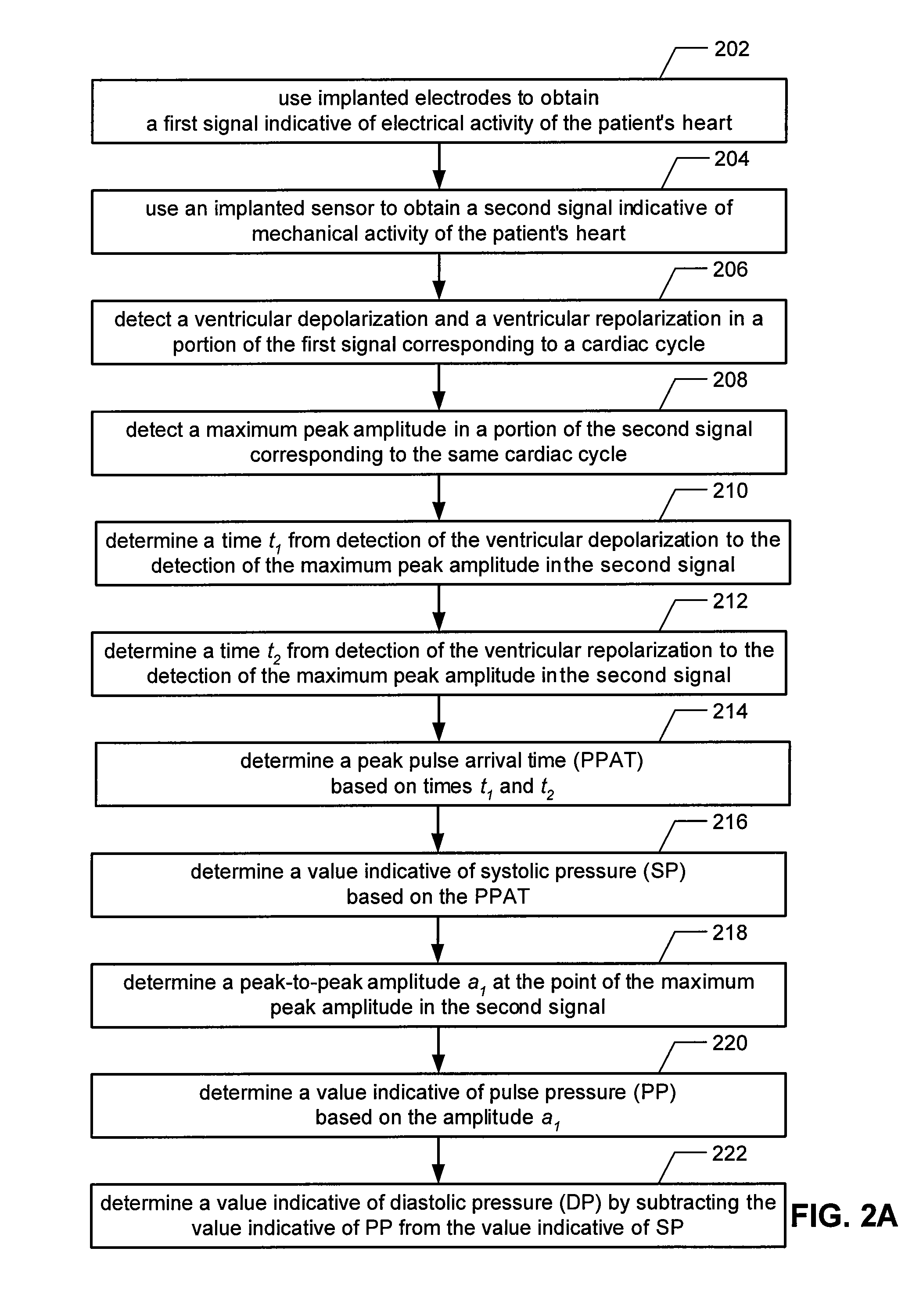
[0077]The implantable PPG sensor 303 outputs a PPG signal similar to signal 108 shown in FIG. 1. More specifically, the output of the light detector 305 can be an analog signal that resembles signal 108. Such a signal can be filtered and / or amplified as appropriate, e.g., to remove respiratory affects on the signal, and the like. Additionally, the signal can be digitized using an analog to digital converter. Based on the PPG signal, and an ECG or IEGM obtained using implanted electrodes, times t1, t2 and peak-to-peak amplitude a1, which were discussed above with reference to FIGS. 1, 2A and 2B, can be determined, thereby enabling measures of SP, DP and MAP to be determined in accordance with embodiments of the present invention.

Problems solved by technology

However, such an approach is slow, requires the intervention of a skilled clinician and does not provide timely readings as it is a measurement at only a single point in time.
While systolic pressure and diastolic pressure can also be obtained in more automated fashions, it is not always practical to obtain measures of pressure using a cuff and pressure transducer combination, especially if the intention or desire is to implant a sensor that can monitor arterial pressure on a chronic basis.
However, an intravascular device may cause problems, such as, embolization, nerve damage, infection, bleeding and / or vessel wall damage.
There are a number of disadvantages to the Finapres technique.
Further, maintaining continuous cuff pressure causes restriction of the circulation in the finger being used, which is uncomfortable when maintained for extended periods of time.
Accordingly, the Finapres technique is not practical for chronic use.
Additionally, because of the need for a pneumatic cuff, a Finapres device can not be used as an implanted sensor.
Simple external blood pressure monitors also exist, but they do not offer continuous measurement and data logging capability.
Additionally, portable external miniature monitors that automatically log blood pressure data exist, but these devices can only store a day or so of data and require clinician interaction to download and process the measured data.

Method used


Image

  • Implantable Systemic Blood Pressure Measurement Systems and Methods
  • Implantable Systemic Blood Pressure Measurement Systems and Methods
  • Implantable Systemic Blood Pressure Measurement Systems and Methods

Examples


Embodiment Construction

[0025]The following description is of the best modes presently contemplated for practicing various embodiments of the present invention. The description is not to be taken in a limiting sense but is made merely for the purpose of describing the general principles of the invention. The scope of the invention should be ascertained with reference to the claims. In the description of the invention that follows, like numerals or reference designators will be used to refer to like parts or elements throughout. In addition, the first digit of a reference number identifies the drawing in which the reference number first appears.

[0026]It would be apparent to one of skill in the art that the present invention, as described below, may be implemented in many different embodiments of hardware, software, firmware, and / or the entities illustrated in the figures. Any actual software, firmware and / or hardware described herein is not limiting of the present invention. Thus, the operation and behavior...


PUM


Abstract

Implantable systems, and methods for use therewith, for monitoring arterial blood pressure on a chronic basis are provided herein. A first signal indicative of electrical activity of a patient's heart, and a second signal indicative of mechanical activity of the patient's heart, are obtained using implanted electrodes and an implanted sensor. By measuring the times between various features of the first signal relative to features of the second signal, values indicative of systolic pressure and diastolic pressure can be determined. In specific embodiments, such features are used to determine a peak pulse arrival time (PPAT), which is used to determine the value indicative of systolic pressure. Additionally, a peak-to-peak amplitude at the maximum peak of the second signal, and the value indicative of systolic pressure, can be used to determine the value indicative of diastolic pressure.

Description

FIELD OF THE INVENTION[0001]Embodiments of the present invention relate to implantable systems for monitoring arterial blood pressure, and methods for use therewith.BACKGROUND OF THE INVENTION[0002]A person's circulatory system includes both systemic and pulmonary circulation systems. Pulmonary circulation supplies the lungs with blood flow, while the systemic circulation takes care of all the other parts of the body, i.e. the systemic circulation. The heart serves as a pump that keeps up the circulation of the blood. Both the pulmonary and systemic circulatory systems are made up of arteries, arterioles, capillaries, venules and veins. The arteries take the blood from the heart, while the veins return the blood to the heart[0003]Blood pressure is defined as the force exerted by the blood against any unit area of the vessel wall. The measurement unit of blood pressure is millimeters of mercury (mmHg). Pulmonary and systemic arterial pressures are pulsatile, having systolic and diast...

Claims


Application Information

Patent Timeline
Patent Type & Authority Applications(United States)
IPC IPC(8): A61B5/0215
CPCA61B5/0215A61B5/0285A61B5/0452A61N1/36585A61B2562/0219A61N1/36564A61N1/36578A61B5/6846A61B5/02108A61B5/02116A61B5/02125A61B5/0295A61B5/349A61B5/358A61B5/355
Inventor FAYRAM, TIMOTHY A.FAIN, ERIC S.LEVINE, PAUL A.
Owner PACESETTER INC
Learn More