Arc welding

a technology of arc welding and fume, which is applied in the direction of instruments, soldering devices, auxillary welding devices, etc., can solve the problems that the unlimited exposure to arc welding fume is now considered to be potentially hazardous to the health of the welder, and achieve the effect of reducing the hazards presented

Inactive Publication Date: 2009-03-12
THE BOC GRP PLC
View PDF15 Cites 56 Cited by
  • Summary
  • Abstract
  • Description
  • Claims
  • Application Information

AI Technical Summary

Benefits of technology

[0011]The location remote from the arc is preferably one close to and at the level of the welder's face. In this way, the welding process can be controlled so as to minimise the hazards presented to the welder. Thus, at least one of the sensors may be incorporated into a helmet or respirator worn by the welder.

Problems solved by technology

Unlimited exposure to arc welding fume is now considered to be potentially hazardous to the health of the welder.

Method used


Image

  • Arc welding
  • Arc welding

Examples


Embodiment Construction

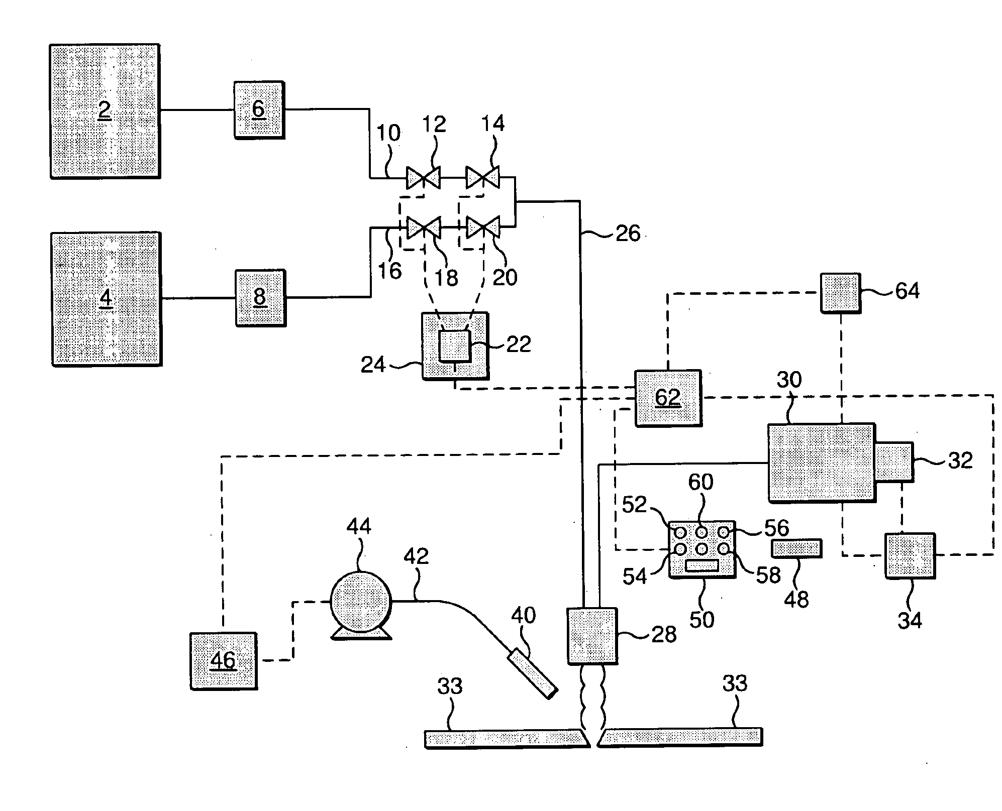
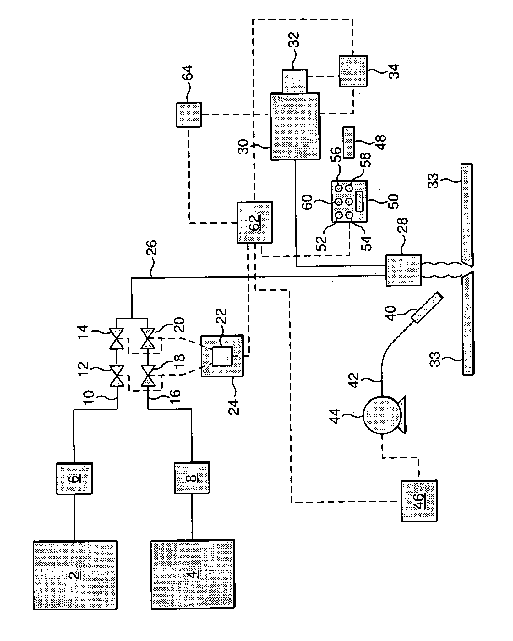
[0019]Referring to the drawing, a welding apparatus of a conventional kind includes a source 2 of a first component of a gaseous shielding mixture and a source 4 of a second component of the mixture. As shown, in the drawing, both the sources 2 and 4 take the form of vacuum-insulated vessels containing the desired shielding gas components in liquid state. For example, the vessel 2 may contain liquid argon and the vessel 4 liquid carbon dioxide. The storage vessel 2 is associated with a vaporiser 6 and the storage vessel 4 with a vaporiser 8. The vaporiser 6 is preferably of a kind that causes the liquid argon to flow through a heat exchange coil which is exposed to a flow of ambient air. The vaporiser 8 is preferably an electrically heated vaporiser. Resulting vaporised argon flows from the vaporiser 6 to a pipeline 10 in which are disposed an isolation valve 12 and a flow control valve 14. Similarly, vaporised carbon dioxide flows from the vaporiser 8 along a pipeline 16 in which a...


PUM

PropertyMeasurementUnit
diameteraaaaaaaaaa
concentrationaaaaaaaaaa
flow rateaaaaaaaaaa

Abstract

In the control of a semi-automatic or automatic electric arc welding operation, the concentration in the atmosphere remote from the arc of a plurality of fume components is monitored. Control signals are fed or transmitted to at least one process control means which is programmed to adjust a plurality of operational parameters in response to the control signals.

Description

CROSS REFERENCE TO RELATED APPLICATIONS[0001]This application claims priority from International Patent Application Serial No. PCT / GB2006 / 050272, filed 5 Sep. 2006 (published as WO 2007 / 029033 A1, with publication date 15 Mar. 2007), which claims priority from British Patent 0518458.5, filed 9 Sep. 2005.BACKGROUND OF THE INVENTION[0002]This invention relates to a method of an apparatus for controlling a semi-automatic or automatic electric arc welding operation.[0003]Electric arc welding is a well known industrial operation which makes use of an electric arc to generate the heat necessary to melt an electrode or filler material which provides the weld metal. In semi-automatic or automatic electric arc welding the electrode or filler material takes the form of a coil of wire which is continuously fed to the arc. Gas Metal Arc Welding (GMAW), commonly called Metal Inert Gas (MIG) welding, is a type of welding which utilises a welding gun or torch through which a continuous wire electr...

Claims


Application Information

Patent Timeline
Patent Type & Authority Applications(United States)
IPC IPC(8): B23K9/00B23K9/095B23K9/32B23K37/00
CPCB23K9/0956B23K9/0953B23K9/095B23K9/32B23K37/00G01N33/00
Inventor DUFFY, JOHN
Owner THE BOC GRP PLC
Why Eureka
Try Eureka