Angular position detector and rotary electric device drive unit including the same

Inactive Publication Date: 2009-03-12
TOYOTA JIDOSHA KK
View PDF5 Cites 11 Cited by
  • Summary
  • Abstract
  • Description
  • Claims
  • Application Information

AI Technical Summary

Benefits of technology

[0029]According to the second aspect of the invention, because less processing power is required for detecting the angular position, the rotary electric device control unit can be configured at low cost. In addition, the rotary electric device control unit is also better able to reliably control the rotary electric device even when the rotary electric device runs at a high speed.
[0030]According to the invention, it is possible to provide the angular position detector that can be configured at low cost and that can accurately

Problems solved by technology

However, the inclusion of such circuitry in the R/D converter 306 greatly adds to the cost of the component, and consequently increases the total production cost of the motor drive unit.
With the above-mentioned technologies, however, a large amount of sample data is needed to accurately detect the angular position of the rotor when the signals SIN and COS are converted into digital signals to accurately even through the noise present in the signals SIN and COS is removed.
As a result, the processing load placed on the microcomputer increases due to the sheer quantity of sample data, which may cause delays in

Method used


Image

  • Angular position detector and rotary electric device drive unit including the same
  • Angular position detector and rotary electric device drive unit including the same
  • Angular position detector and rotary electric device drive unit including the same

Examples


Embodiment Construction

[0045]Hereafter, an embodiment of the invention will be described in detail with reference to accompanying drawings. The same or corresponding portions will be denoted by the same reference numerals.

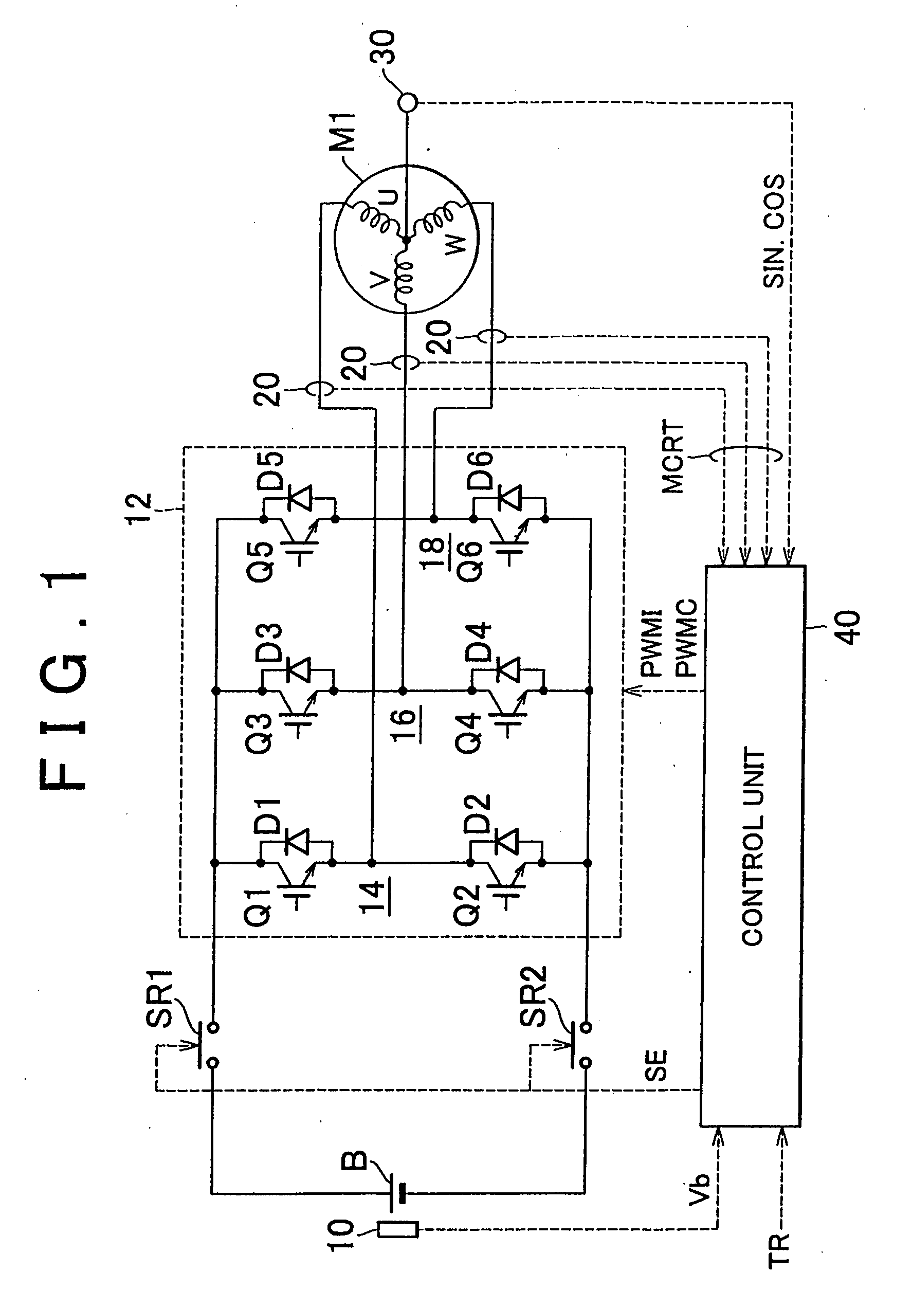
[0046]FIG. 1 illustrates the schematic block diagram of a motor drive unit including an angular position detector according to the embodiment of the invention.

[0047]As shown in FIG. 1, the motor drive unit includes a direct-current power supply (hereinafter, referred to as a “DC power supply”) B, a voltage sensor 10, an inverter 12, a current sensor 20, a resolver 30, and a control unit 40.

[0048]An alternating-current motor (hereinafter, referred to as an “AC motor”) M1 is provided to drive the drive wheels of a hybrid vehicle or an electric vehicle. The AC motor M1 may function as an electric power generator driven by an engine, or as an electric motor for the engine. For example, the AC motor M1 can be used to start the engine.

[0049]The inverter 12 includes a U-phase arm 14, a V-phase ...


PUM


Abstract

The invention provides an angular position detector that can be configured at low cost and that accurately detects the angular position of a rotor in a rotary electric device and permits reliable control thereof even when the rotary electric device runs at a high speed. The angular position detector includes a resolver that outputs a signal indicating the rotational angle of the rotor and a signal processing circuit that calculates the rotational angle of the rotor based on the signal output from the resolver. The signal processing circuit samples output signals from the resolver at predetermined intervals and converts the signal into a digital signal. By calculating the angular speed according to the digital signal output from the resolver, the computation process is simpler, and can be performed using a microcomputer with less processing power, which reduces the component costs for the angular position detector.

Description

[0001]This is a 371 national phase application of PCT / IB2006 / 001221 filed 10 May 2006, claiming priority to Japanese Patent Application No. 2005-138670 filed 11 May 2005, the contents of which are incorporated herein by reference.BACKGROUND OF THE INVENTION[0002]1. Field of the Invention[0003]The invention relates generally to an angular position detector and a rotary electric device drive unit including the same. More specifically, the angular position detector of the invention can be configured at low cost, and can accurately detect the angular position of a rotor in a rotary electric device even when the rotary electric device runs at a high speed.[0004]2. Description of the Related Art[0005]Japanese Patent Application Publication No. JP-A-2001-86786, Japanese Patent Application Publication No. JP-A-07-79589, Japanese Patent Application Publication No. JP-A-2002-350180, and Japanese Patent Application Publication No. JP-A-2004-12387 describe motor drive units for driving a motor,...

Claims


Application Information

Patent Timeline
IPC IPC(8): G01B7/30G01D5/244
CPCG01D5/2073G01D5/204G01D5/244G01D5/00
Inventor NAGAMOTO, MAKOTO
Owner TOYOTA JIDOSHA KK
Why Eureka
Try Eureka