Wind turbine, yaw system controller and yaw system for a wind turbine and method of reducing the acting on such a yaw system

a technology of yaw system and wind turbine, which is applied in the direction of rotors, vessel construction, marine propulsion, etc., can solve the problems of large yaw moment acting of wind turbine rotor, large oscillating load on the yaw system, and the requirement for yaw drive system to be of very substantial dimensions, so as to minimise the yaw moment acting and minimise the load acting

Inactive Publication Date: 2009-03-12
SIEMENS AG
View PDF7 Cites 62 Cited by
  • Summary
  • Abstract
  • Description
  • Claims
  • Application Information

AI Technical Summary

Benefits of technology

[0011]With respect to the mentioned state of the art it is an objective of the present invention to provide a method of reducing the loads acting on a wind turbine yaw system due to yawing moments which are induced to the yaw system by a rotor. It is a further object of the present invention to provide an improved yaw system controller and a yaw system for a wind turbine. It is a still further objective of the present invention to provide an improved wind turbine.

Problems solved by technology

Due to turbulence and other flow irregularities the wind turbine rotor experiences large yawing moments.
When trying to retain the rotor in its correctly oriented position the yaw system is exposed to large oscillating loads.
However, on large wind turbines this means that the yaw drive system has to be of very substantial dimensions since turbulence eddies or other flow irregularities may occasionally give rise to very large yawing moments on the turbine rotor and hence the nacelle.
In such situations the yaw drive system cannot carry out yawing in a desired direction and may even be forced backwards in the opposite direction.
Even if it is accepted that a yaw drive system is not rated for the worst case scenarios such a system tends to be large, heavy and expensive.
However, these arrangements cause two difficulties.
At first, the unavoidable play in the gearing between the geared ring fixed to the tower and the pinions of the yaw drives may cause an oscillating movement and lead to a hammering of the gear mesh which is detrimental to the geared parts.

Method used


Image

  • Wind turbine, yaw system controller and yaw system for a wind turbine and method of reducing the acting on such a yaw system
  • Wind turbine, yaw system controller and yaw system for a wind turbine and method of reducing the acting on such a yaw system
  • Wind turbine, yaw system controller and yaw system for a wind turbine and method of reducing the acting on such a yaw system

Examples


Embodiment Construction

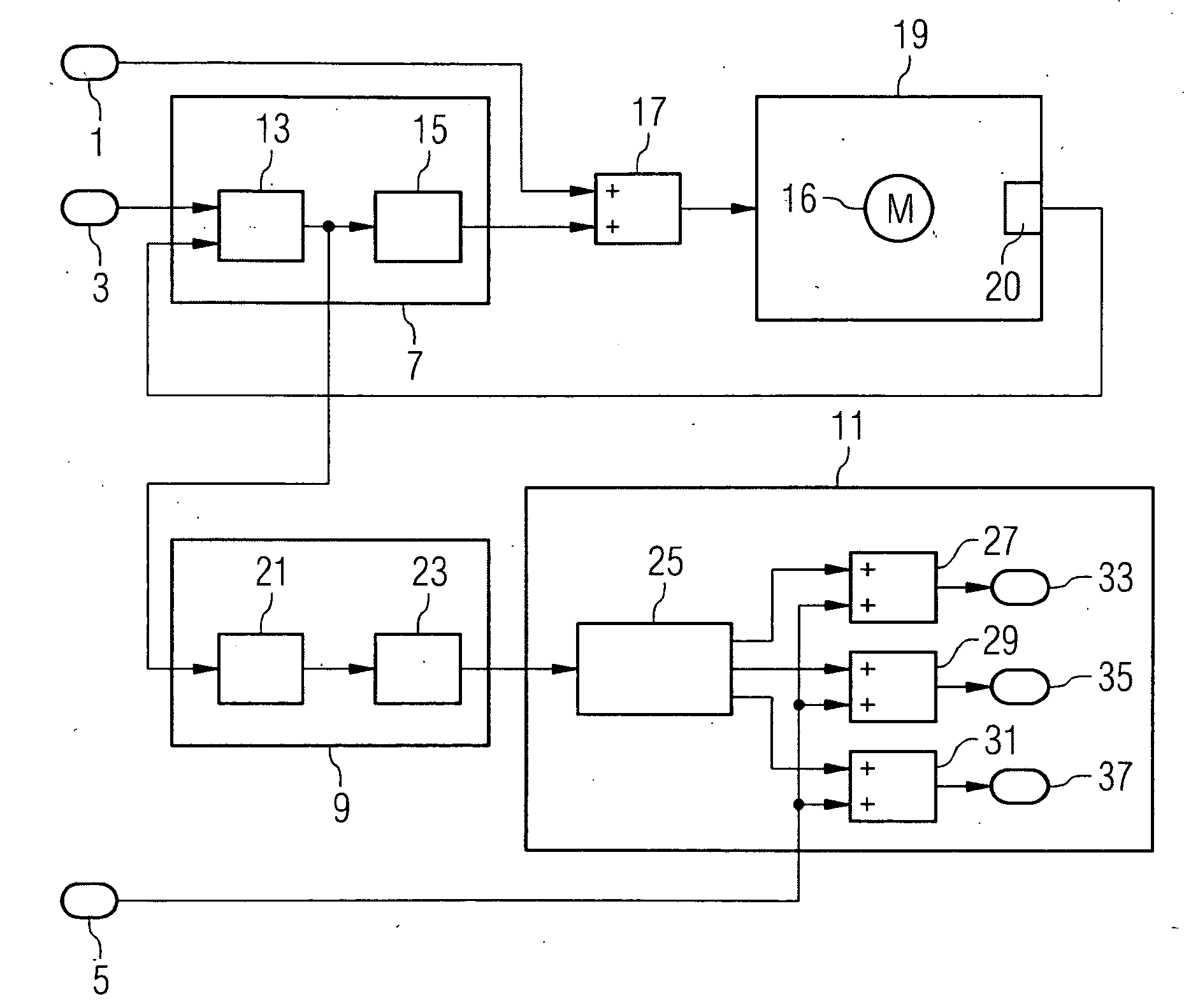
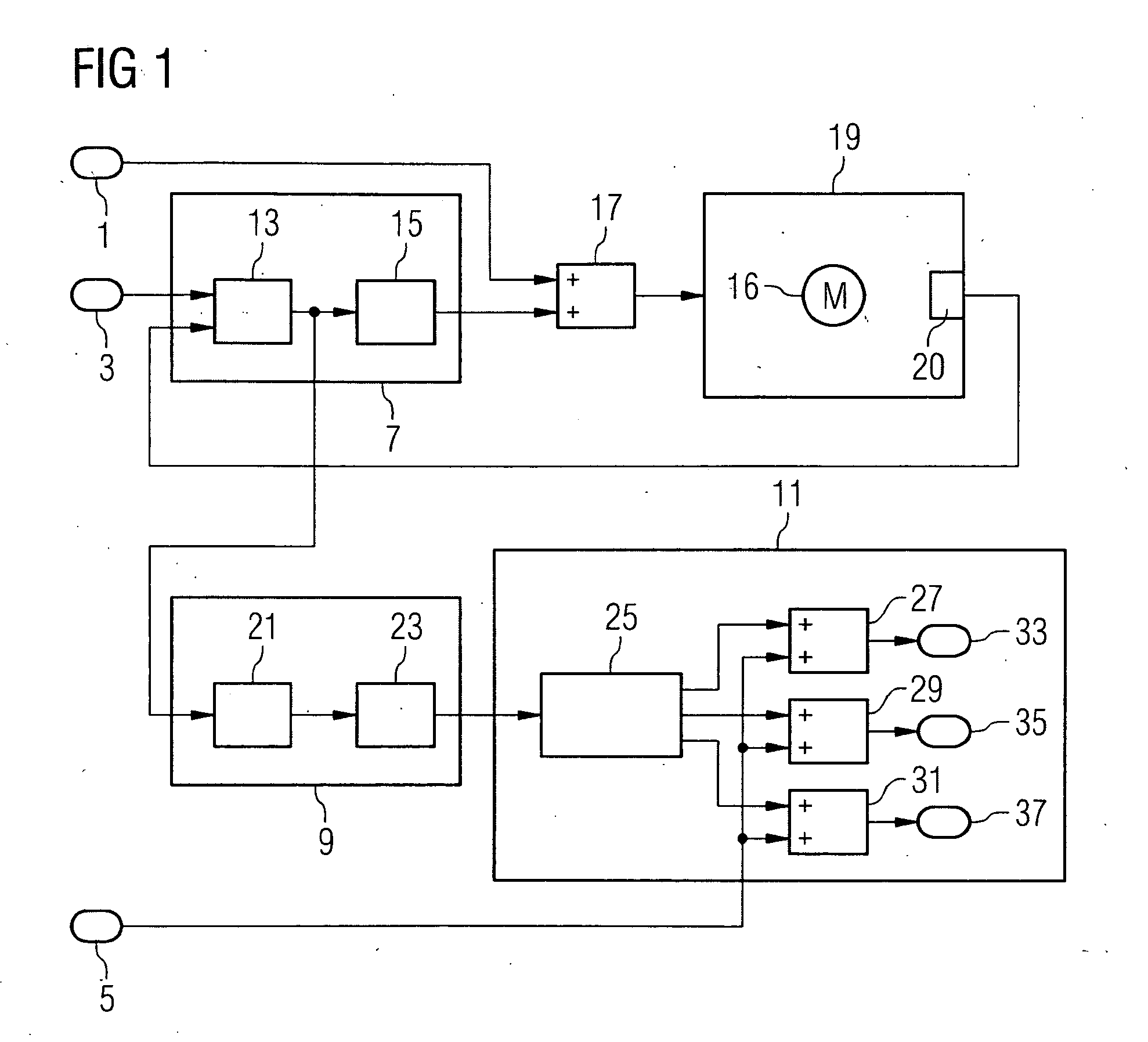
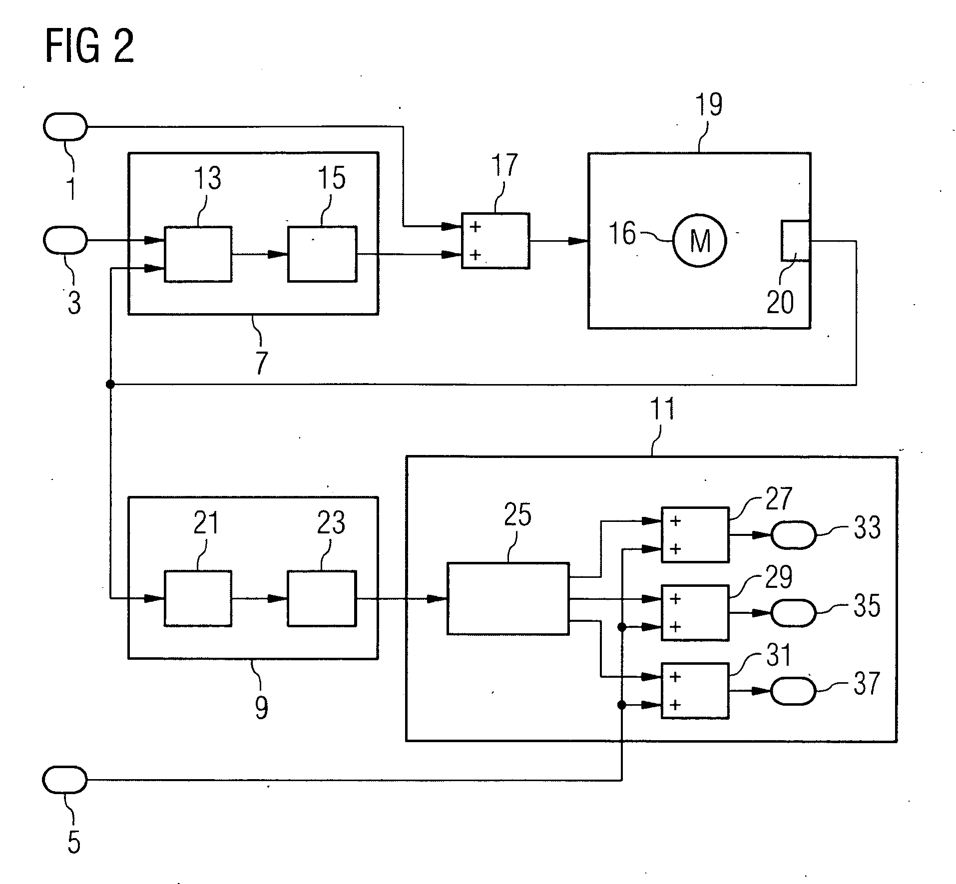
[0038]A first embodiment of the inventive method and the inventive yaw system will be described with respect to FIG. 1. FIG. 1 shows a control system comprising three inputs 1, 3, 5 with the first input receiving a signal representing an aerodynamic torque acting on the rotor when the horizontal rotor axis is misaligned, i.e. a yaw angle occurs. The second input 3 receives a yaw speed reference signal which represents the yaw speed, i.e. the change in the yaw angle, by which the horizontal rotor axis of the rotor shall be rotated to achieve an alignment with the wind direction, i.e. to reduce the yaw angle. The third input receives a common pitch reference signal which sets a common pitch angle for each rotor blade of the wind turbine's rotor. Such a common pitch signal is used to control the power output of the wind turbine.

[0039]The control system further comprises a yaw system controller with a yaw drive controller 7 and a yaw motor load controller 9. It further comprises a pitch...


PUM


Abstract

A method for reducing the loads acting on a wind turbine yaw system due to yawing moments which are induced to the yaw system by a rotor which comprises at least one rotor blade with a pitch control system is provided. In the method, the yawing moment which is induced to the yaw system by the rotor is determined and the pitch of the at least one rotor blade is set based on the detected yawing moment such that the determined yawing moment is reduced.

Description

CROSS REFERENCE TO RELATED APPLICATIONS[0001]This application claims the benefits of European application No. 07017912.2 filed Sep. 12, 2007 and is incorporated by reference herein in its entirety.FIELD OF INVENTION[0002]The present invention relates to a method of reducing the torque acting on a wind turbine yaw system, in particular on at least one yaw drive, due to yawing moments which are induced to the yaw system by a rotor. In addition, the invention relates to a yaw system controller and a yaw system for a wind turbine as well as to a wind turbine.BACKGROUND OF THE INVENTION[0003]Due to turbulence and other flow irregularities the wind turbine rotor experiences large yawing moments. In trying to orient the rotor to the wind the yaw system of a wind turbine has to overcome these large yawing moments in addition to any friction in the yaw bearing. When trying to retain the rotor in its correctly oriented position the yaw system is exposed to large oscillating loads.[0004]The me...

Claims


Application Information

Patent Timeline
Patent Type & Authority Applications(United States)
IPC IPC(8): F03D7/02
CPCF03D7/0204F03D7/0224F03D7/024F03D7/0292Y02E10/723F05B2260/70F05B2270/1095F05B2270/329F03D7/044Y02E10/72
Inventor BIRKEMOSE, BOEGEDAL, PER
Owner SIEMENS AG
Why Eureka
Try Eureka