Gas sensor designed to ensure stability of waterproofing of air flow path

a gas sensor and waterproofing technology, applied in the direction of instruments, measurement devices, electrochemical variables of materials, etc., can solve the problems of thermal deterioration of the air-permeable filter, interference with the improvement of gas sensor productivity, etc., to enhance the resistance to reactive pressure, high heat resistance, durability and mechanical strength

Inactive Publication Date: 2009-03-19
DENSO CORP
View PDF1 Cites 0 Cited by
  • Summary
  • Abstract
  • Description
  • Claims
  • Application Information

AI Technical Summary

Benefits of technology

[0013]It is another object of the invention to provide an improved structure of a gas sensor designed to have high productivity and ensure the waterproofing of an air flow path in the gas sensor.
[0034]The air cover may be made of metal such as stainless steel which is high in heat resistance, durability, and mechanical strength in environments of use of the gas sensor. The use of the metal enhances the resistance to reactive pressure from the elastic member at the crimped recesses.

Problems solved by technology

This requires a lot of steps in the installation of the air-permeable filter 95, thus interfering with the improvement of productivity of the gas sensor 9.
Consequently, use of the gas sensor 9 in the exhaust system of the internal combustion engine for a long time will result in thermal deterioration of the air-permeable filter 95.

Method used


Image

  • Gas sensor designed to ensure stability of waterproofing of air flow path
  • Gas sensor designed to ensure stability of waterproofing of air flow path
  • Gas sensor designed to ensure stability of waterproofing of air flow path

Examples


first embodiment

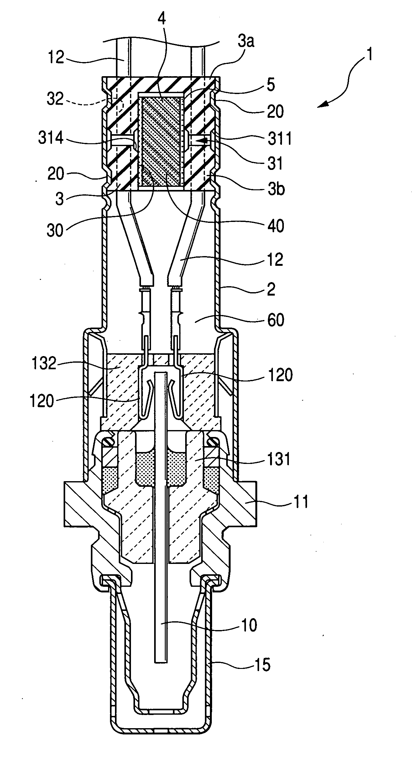
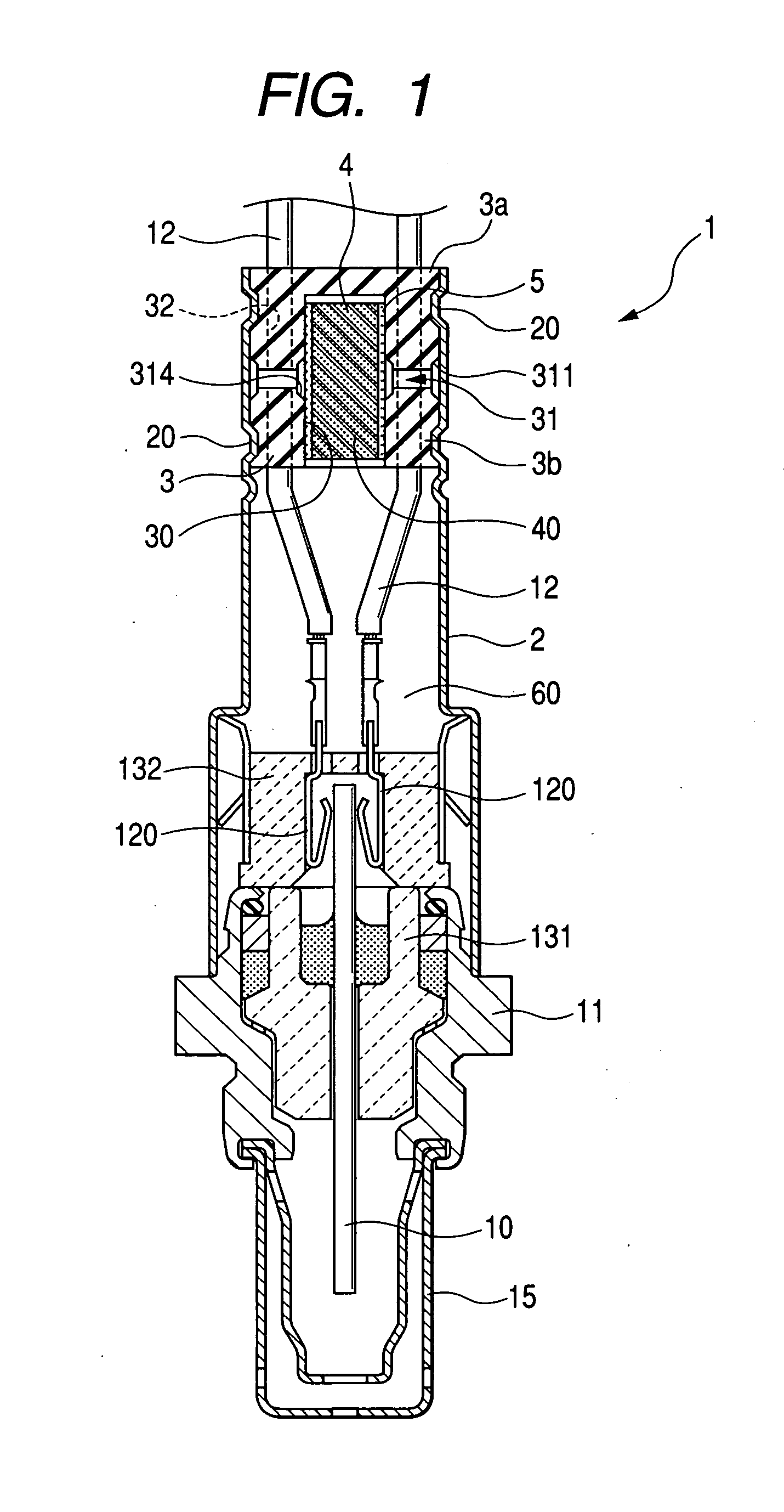
[0054]Referring to the drawings, wherein like reference numbers refer to like parts in several views, particularly to FIG. 1, there is shown a gas sensor 1 according to the invention which may be employed as an oxygen sensor, a NOx sensor, or an air-fuel ratio sensor installed in an exhaust pipe of automotive internal combustion engines.

[0055]The gas sensor 1 has a length with a top end (i.e., a lower end, as viewed in FIG. 1) and a base end (i.e., an upper end, as viewed in FIG. 1) and includes a sensing device 10, a hollow cylindrical housing 11, an air cover 2, leads 12, and an elastic bush 3. The sensing device 10 is sensitive to the concentration of gas and outputs a signal indicative thereof. The housing 11 retains the sensing device 10 therein. The air cover 2 is joined or welded at a top end thereof (i.e., a lower end, as viewed in FIG. 1) to a base end (i.e., an upper end, as viewed in FIG. 1) of the housing 10. The leads 12 extend within the air cover 12 and connect with a...

second embodiment

[0089]FIG. 10 shows the gas sensor 1 according to the invention which is equipped with the cup-shaped sensing device 10.

[0090]The sensing device 10 is made up of a bottomed hollow cylindrical solid electrolyte body 100 and a pair of electrodes (not shown) affixed to an outer and an inner surface, respectively. The solid electrolyte body 100 has formed therein a reference gas chamber 101 into which the air is admitted as a reference gas and within which a heater 102 is disposed.

[0091]The sensing device 10 and the heater 102 have terminals which establish electric connections with the leads 12 through the connector terminals 120. Other arrangements are identical with those in the first embodiment, and explanation thereof in detail will be omitted here.

third embodiment

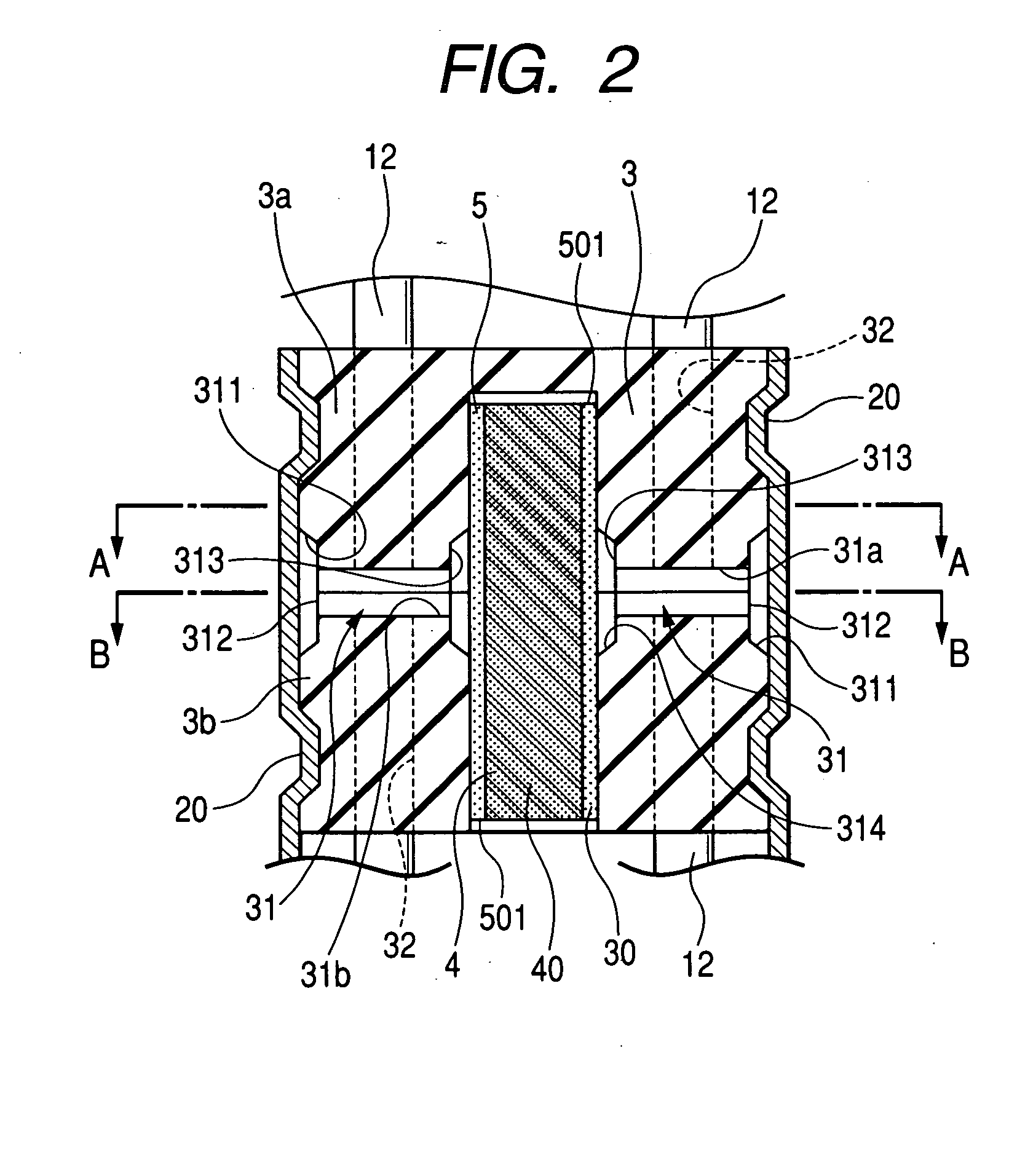
[0092]FIGS. 11 to 14 illustrate an elastic bush 3 installed in the gas senor 1 according to the invention, 5 The elastic bush 3 is made up of the cylindrical blocks 3a and Sb. The block 3a has four protrusions or ridges 33 formed on the top end thereof which faces the top end of the gas sensor 1. The ridges 33 are, as illustrated in FIG. 14, located at a regular interval and taper toward the block 3b. In other words, each of the ridges 33 has a triangular sectional area which traverses the axis of the elastic rubber 3 and decreases toward the top thereof.

[0093]The blocks 3a and 3b are, as illustrated in FIGS. 11 and 13, coupled with each other in contacting abutment of the ridges 3 with the upper end of the block 3b. The assembly of the blocks 3a and 3b defines the vertical hole 30 in which the assembly of the air-permeable filter 5 and the support 4 is installed. The assembly of the blocks 3a and 3b also defines each of the horizontal holes 31 between adjacent two of the ridges 33....


PUM

PropertyMeasurementUnit
lengthaaaaaaaaaa
concentrationaaaaaaaaaa
mechanical pressureaaaaaaaaaa

Abstract

A gas sensor equipped with an elastic member which is disposed hermetically in an open end of an air cover joined to a housing. The elastic member has a vertical hole, an air flow path, and lead-retaining holes through which leads pass to establish electric connections between a sensing device and an external device. The air flow path extends from the vertical hole to an outer peripheral surface of the elastic member to direct air having entered at air inlets to the vertical hole. An assembly of an air-permeable filter and a support is fit elastically in the vertical hole of the elastic member, thereby asserting the stability of adhesion between the vertical hole and the filter even if the filter is thermally deteriorated to ensure the waterproofing of the gas sensor.

Description

CROSS REFERENCE TO RELATED DOCUMENT[0001]The present application claims the benefit of Japanese Patent Application No. 2007-68675 filed on Mar. 16, 2007, the disclosure of which is incorporated herein by reference.BACKGROUND OF THE INVENTION[0002]1. Technical Field of the Invention[0003]The present invention relates generally to an improved structure of a gas sensor which measures the concentration of gas to provide a signal indicative thereof, and more particularly to such a gas sensor designed to ensure the stability of waterproofing or watertight sealing of an air flow path in the gas sensor[0004]2. Background Art[0005]There are known gas sensors installed in an exhaust system of automotive internal combustion engines to measure the concentration of oxygen (O2) contained in exhaust emissions. For example, Japanese Patent First Publication No. 11-248671 discloses such a type of gas sensors as illustrated in FIG. 17 The gas sensor 9 is equipped with a sensing device 910 working to ...

Claims


Application Information

Patent Timeline
Patent Type & Authority Applications(United States)
IPC IPC(8): G01N27/26
CPCG01N27/407
Inventor YAMAUCHI, MASANOBU
Owner DENSO CORP
Why Eureka
Try Eureka