On board secondary propulsion system for an aircraft

Inactive Publication Date: 2009-03-19
THE BHARGAVA FAMILY TRUST DATED JUNE 14 1996 +1
View PDF16 Cites 21 Cited by
  • Summary
  • Abstract
  • Description
  • Claims
  • Application Information

AI Technical Summary

Benefits of technology

[0033]Any of these embodiments of the on board power secondary propulsion system according to the present invention may be used in conjunction with the main aircraft engines during taxiing and

Problems solved by technology

In modern aircraft, weight space, and costs are highly important, whether the aircraft is for commercial, private or military applications.
Conventional power systems that provide ground services for environmental cooling, engine start, ground system check-out, and emergency power (often referred to as auxiliary power units and emergency power units), while necessary, are also considered somewhat of a burden, as they generally only add weight to the aircraft while it is in flight.
Reliability and maintainability of aircraft syste

Method used


Image

  • On board secondary propulsion system for an aircraft
  • On board secondary propulsion system for an aircraft
  • On board secondary propulsion system for an aircraft

Examples


first embodiment

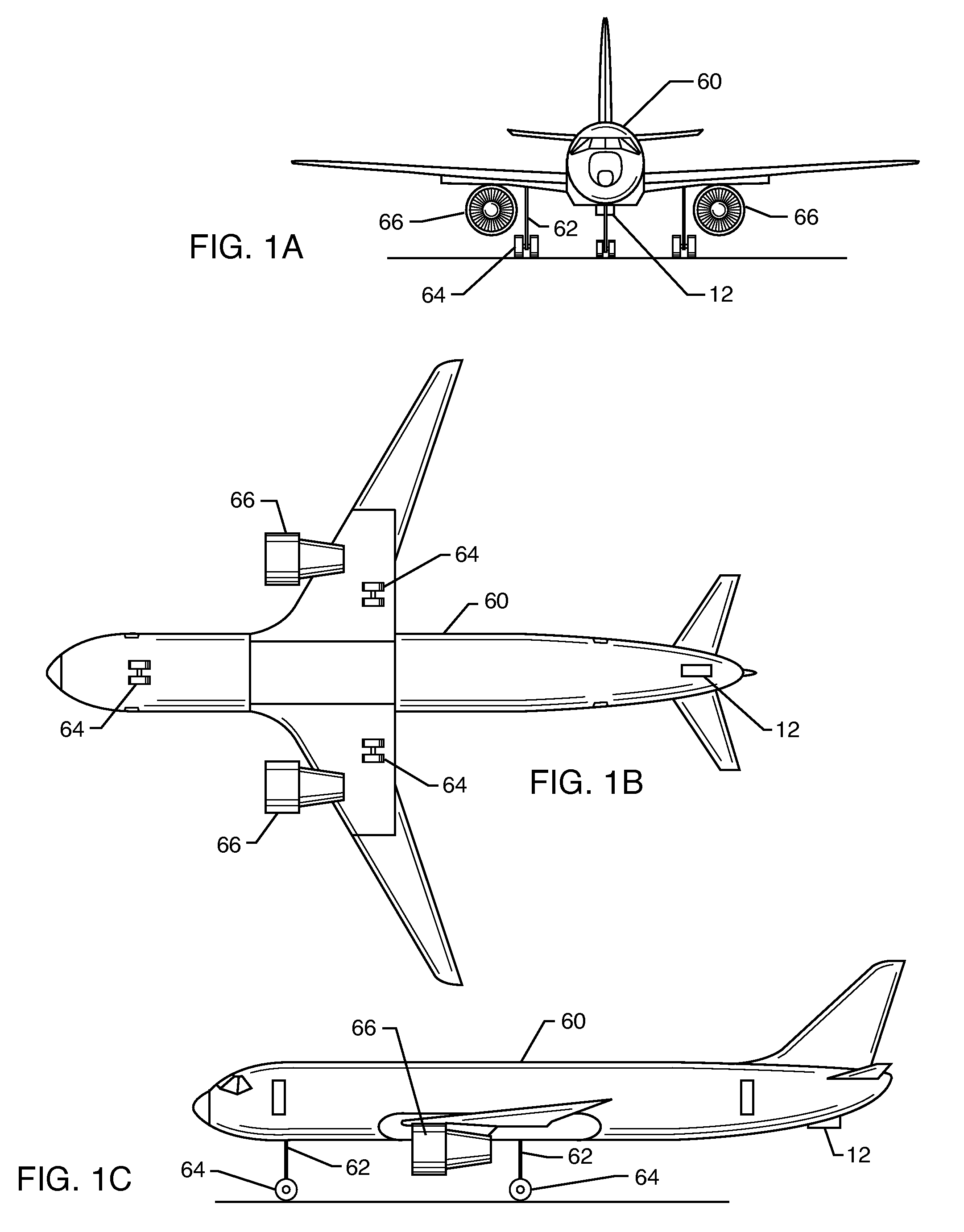
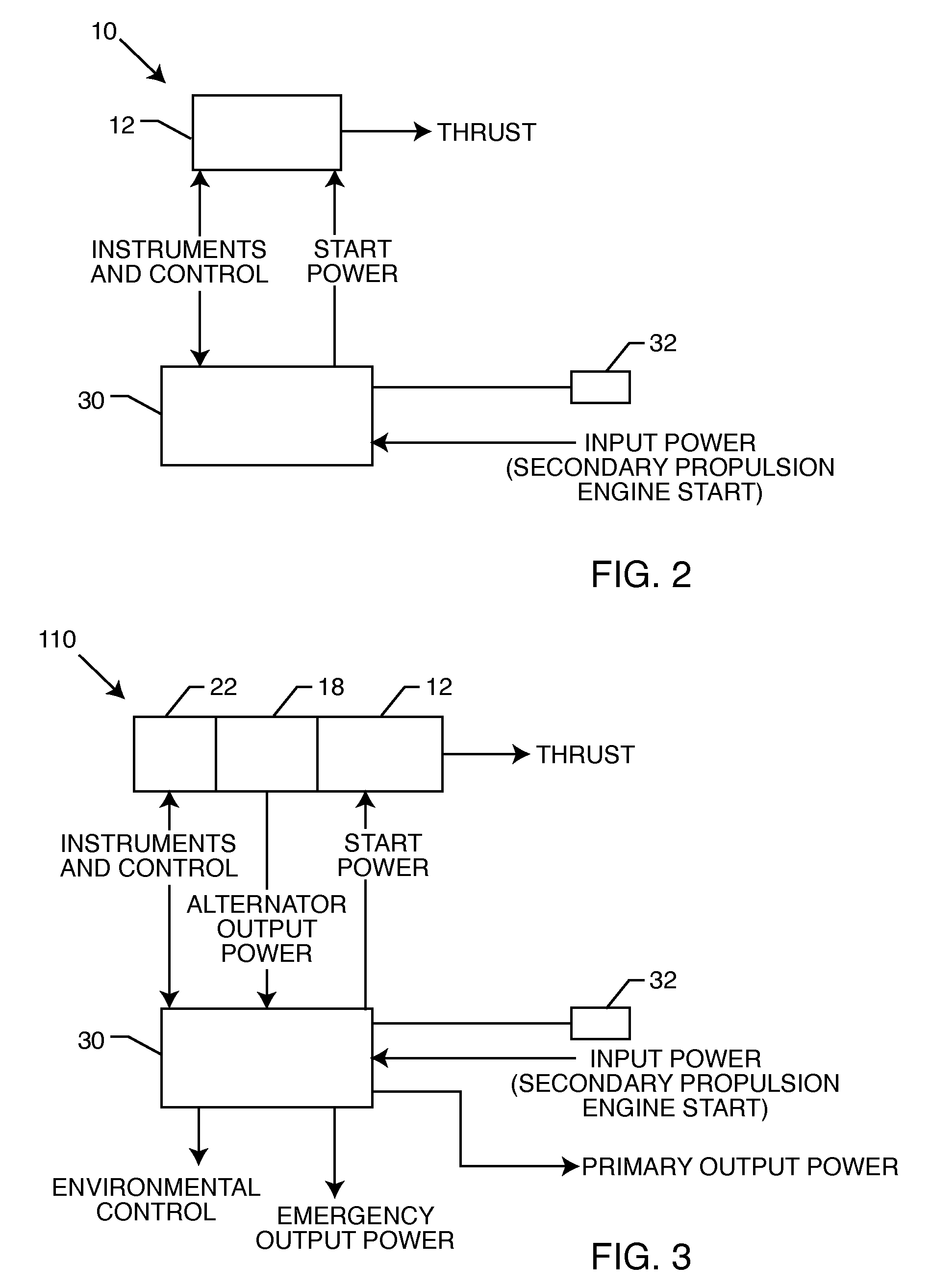
[0048]FIG. 2 schematically illustrates a secondary propulsion system 10 in accordance with the present invention. System 10 includes driver 12, which may be a turbine engine, for example, which provides output power for taxiing aircraft 60 without having to start the main flight engine(s) 66 of the aircraft.

[0049]Driver 12 is in communication with control system 30, which also includes control panel 32 having the appropriate instrumentation, controls, indicator lights, and switches typical of such systems. Such control systems are well-known and quite common to those having skill in the art and the details of such a control system need not be discussed here. Also, the design of turbine engines, APU's, EPU's, ECS's, ESS's, gearboxes and engine mounting structures are also well-known and quite common to those having skill in the art and the details of such systems, equipment and structures need not be discussed here. In the first embodiment 10 of the invention, control system 30 provi...

second embodiment

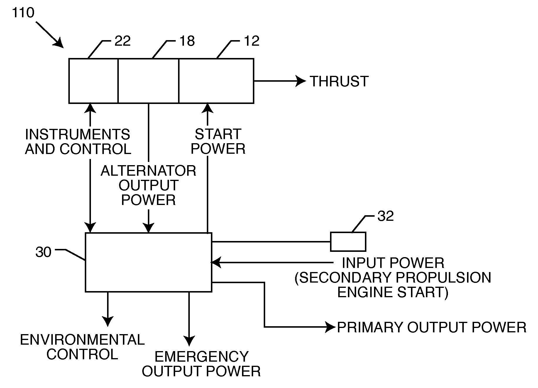
[0052]In this second embodiment of the invention, secondary propulsion system 110 includes driver 12, which would be designed to have a high speed power shaft (not shown). A high-speed alternator 18 would be mounted on the high-speed power shaft. Alternator 18, as is well known in the art, may also act as a starter / generator. Alternator 18 may be used in conjunction with an environmental control unit 22, which provides conditioned air where required in various compartments of the aircraft.

[0053]Driver 12 is in communication with control system 30, which also includes control panel 32 having the appropriate instrumentation, controls, indicator lights, and switches typical of such systems. As has been previously discussed, such control systems are well known and quite common to those having skill in the art and the details of such a control system need not be discussed here. Also as previously discussed, the design of turbine engines, APU's, EPU's, ECS's, ESS's, gearboxes and engine m...


PUM


Abstract

An on board secondary propulsion system for an aircraft provides the capability of taxiing the aircraft on the ground without using the main aircraft engine(s). The power system includes a small driver mounted on the aircraft. In one embodiment of the invention, the driver may be mounted at any desirable location on the aircraft and is designed to provide sufficient thrust to taxi the aircraft. Such a suitable system may be provided as original equipment to an aircraft or retrofitted to existing aircraft. In a further embodiment of the invention, the on board secondary propulsion system, in addition to the taxiing function, may be incorporated with an alternator to provide electrical power, an environmental control unit, and an emergency power unit as desired. The system may also be used to supplement the main aircraft engines as necessary during takeoff and climb to further reduce fuel consumption, noise, engine emissions, maintenance costs and extend the life of the main aircraft engines. Additionally the thrust provided by the secondary propulsion system could essentially reduce the required takeoff distance of an aircraft, thus allowing the use of shorter runways.

Description

RELATED APPLICATIONS[0001]This application is a Continuation-in-Part application of patent application Ser. No. 11 / 683,711, filed Mar. 8, 2007, and incorporates Disclosure Document No. 597568, entitled “Auxiliary Power System For An Aircraft,” filed Mar. 17, 2006, by reference in its entirety.BACKGROUND OF THE INVENTION[0002]1. Field of the Invention[0003]The present invention relates to the field of auxiliary or secondary power systems for aircraft and, in particular, to secondary on board propulsion system that provides the capability of taxiing an aircraft without having to start or use the main aircraft engine(s).[0004]2. General Background and State of the Art[0005]In modern aircraft, weight space, and costs are highly important, whether the aircraft is for commercial, private or military applications. It is known, for example, that up to 15% of the costs to operate an aircraft are typically spent while the aircraft is on the ground. Conventional power systems that provide grou...

Claims


Application Information

Patent Timeline
IPC IPC(8): B64D41/00
CPCB64C25/405Y02T50/823Y02T50/44B64D41/00Y02T50/40Y02T50/80
Inventor BHARGAVA, BRIJ B.
Owner THE BHARGAVA FAMILY TRUST DATED JUNE 14 1996
Why Eureka
Try Eureka