Method for generating quantitative images of the flow potential of a region under investigation

a flow potential and quantitative technology, applied in the field of generating quantitative images of the flow potential of a region under investigation, can solve the problems of difficult detection, difficult to detect, and difficulty in detecting non-limiting flow coronary lesion

Inactive Publication Date: 2009-03-19
AMID SRL
View PDF2 Cites 63 Cited by
  • Summary
  • Abstract
  • Description
  • Claims
  • Application Information

AI Technical Summary

Problems solved by technology

This differential approach has however several major drawbacks which are mainly due to the fact that it consists of single local measurements that are not informative of the spatial distribution of flow in a region under analysis, but only of the capability (reserve) that single conduits have to increase the flow.
When structures having a large number of small conduits or permeable bodies have to be analysed, such methodology requires a distinct differential analysis for each of the flow patterns that can be identified which is a rather complex if not impracticable task for very complex structures.
When a coronary artery has a critical obstruction it becomes unable to deliver the proper amount of oxygen and nutrients to the interested region causing ischemia.
Even relevant coronary obstruction (generally up to 75%) may be asymptomatic at rest and sometimes are difficult to detect in the clinical practice.
The diagnosis of non-limiting flow coronary lesion is still a challenge in the clinical practice.
The invasive methods are still quite expensive, are available only in largest medical centers and, even now, imply a little but actual risk of serious complications.
Non invasive methods of nuclear medicine (like SPECT or PET) are expensive too, require the administration of radioactive isotopes and have a limited repeatability.
In these cases, being unable to visualize the microcirculation, also the invasive methods fail to detect the pathological condition.
However CFR, being a local differential analysis, cannot determine a real estimate of the actual flow of the microcirculation of the myocardium.
This results in a non accurate evaluation of a necrosis due for example to stroke.
However, once such stenosis is removed, for example by using a stent or with angioplasty, the flow in the diseased artery becomes normal again and CFR cannot help evaluate if the micro-circulation is irremediably compromised and if such zone of the myocardium is no longer able to react to an increased demand for blood flow under stress as no information of the spatial distribution of blood flow in the myocardial microcirculation can be determined with CFR.
Furthermore not all the coronary vessels are easily visible during a standard echo examination and not in all patients is possible to see the coronary flow with colour Doppler thus limiting the application of CFR analysis only to those coronaries that can be reached in a trans-thoracic projection, namely the left anterior descending coronary artery and the right coronary artery
This approach has however several major drawbacks as the perfusion is a measure of brightness and not of blood flow.
Furthermore no information can be derivable on the capacity of a perfused object or organ to react to a demand of an increased fluid flow.

Method used


Image

  • Method for generating quantitative images of the flow potential of a region under investigation
  • Method for generating quantitative images of the flow potential of a region under investigation
  • Method for generating quantitative images of the flow potential of a region under investigation

Examples


Embodiment Construction

[0056]For the purposes of promoting an understanding of the disclosure, reference will now be made to the embodiments illustrated in the drawings and specific language will be used to describe the same. It will nevertheless be understood that no limitation of the scope of the disclosure is thereby intended, such alterations and further modifications in the illustrated device and its use, and such further applications of the principles of the disclosure as illustrated therein being contemplated as would normally occur to one skilled in the art to which the disclosure relates.

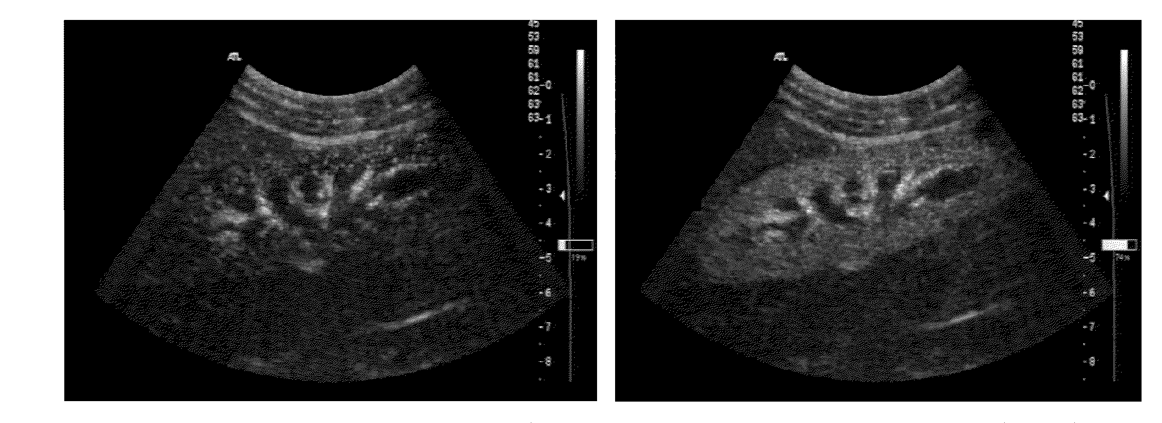
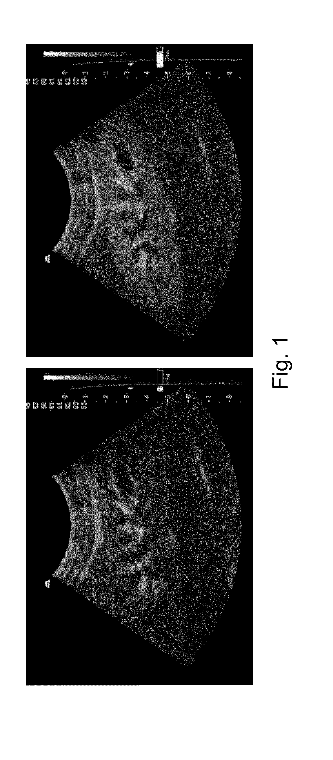
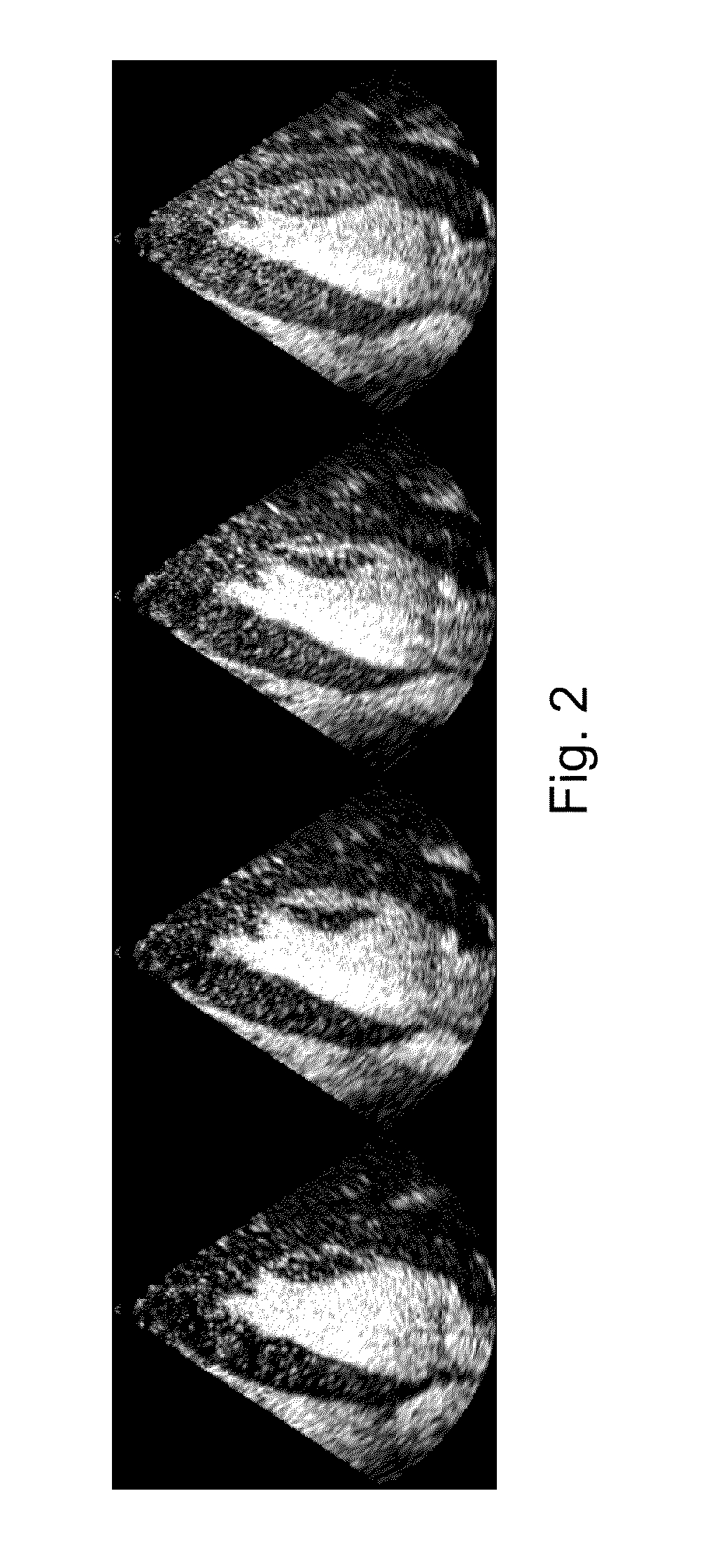
[0057]The invention will be now described with reference to bi-dimensional ultrasound images of organs, particularly the heart, however the skilled person would appreciate that the inventive concept can be applied to process any kind of sequence of images of bodies or regions perfused by a fluid from which quantification images of the spatial distribution of flow can be determined.

[0058]With reference to FIGS. 1 ...


PUM


Abstract

The invention relates to a method for generating images representative of the flow potential of a permeable body. The following steps are part of the disclosed method. First, providing a first sequence of digital images of the body perfused by a fluid at a rest condition. Then extracting a first quantification image of the spatial distribution of flow of the fluid in the body at the rest condition, the first quantification image being defined by pixel values. Next, providing a second sequence of digital images of the body perfused by the fluid at a stress condition. Then extracting a second quantification image of the spatial distribution of flow of the fluid in the body at the stress condition, the second quantification image being defined by pixel values. Then, combining the two quantification images to obtain an image defined by pixel values.

Description

CROSS REFERENCES TO RELATED APPLICATIONS[0001]This application claims priority to European Patent Application No. EP 07116539.3, filed Sep. 17, 2007, entitled “METHOD FOR GENERATING QUANTITATIVE IMAGES OF THE FLOW POTENTIAL OF A REGION UNDER INVESTIGATION”. This reference is expressly incorporated by reference herein, in its entirety.BACKGROUND OF THE INVENTION[0002]The present invention relates to a method for generating images of a region under investigation where the image information is related to the capability of such region to allow the flow of a fluid.[0003]It is generally known that the capability of non-rigid pipes or conduits to allow a fluid to pass through can be determined by measuring the flow when the fluid is in a steady state condition and during transient state when the fluid is forced to flow at an increased rate. The differential value thus obtained is an indirect evaluation of the capability of the conduits to deform to comply with an increased demand of fluid ...

Claims


Application Information

Patent Timeline
Patent Type & Authority Applications(United States)
IPC IPC(8): G06K9/00
CPCA61B5/055A61B6/481A61B6/503A61B6/504A61B8/0883A61B8/06A61B8/0891A61B8/5238A61B6/507A61B6/5235
Inventor PEDRIZZETTI, GIANNITONTI, GIOVANNIMARCHESE, EMIDIO
Owner AMID SRL
Why Eureka
Try Eureka