Four-position rocker switch for electrosurgical handpiece

a rocker switch and handpiece technology, applied in the field of surgical devices, can solve the problems of delay in the performance of a mode by the control unit or the performance of a mode by the electrical instrument, and achieve the effects of improving both the quality and efficiency of the surgical procedure, avoiding erroneous control of the apparatus, and increasing the ease of operation of the apparatus

Active Publication Date: 2009-03-19
ERBE ELEKTROMEDIZIN GMBH
View PDF7 Cites 29 Cited by
  • Summary
  • Abstract
  • Description
  • Claims
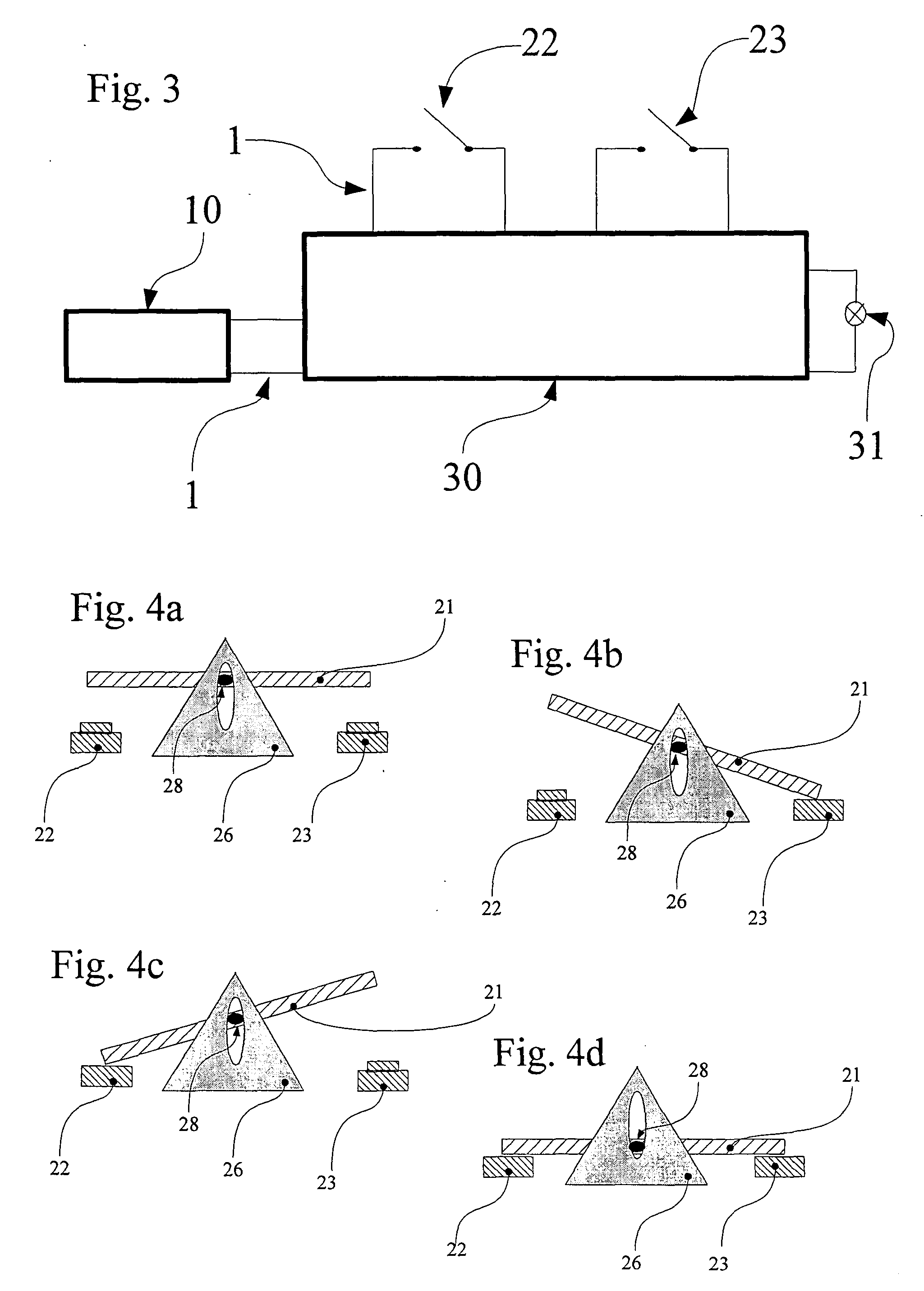
  • Application Information

AI Technical Summary

Benefits of technology

[0006]One advantage of the invention thus resides in the fact that while the surgical apparatus is in use, there is no need to reach around the instrument or even to set it down. This increases the ease of operation of the apparatus, largely excludes the possibility that it will be erroneously controlled because the wrong key has been actuated, and improves both quality and efficiency of the surgical procedure, because the individual modes are rapidly accessible.
[0007]It is advantageous for the surgical apparatus that the control unit be designed so that the setting of at least one function position is delayed by a prespecified latency. This means that there is at least one function position that does not elicit an immediate response when detected by the control unit. That is, the control unit delays either the performance of a mode by the electrical instrument, or the change of mode itself. Thus, the physician himself has the opportunity independently to detect a defective operation of the switching rocker and to react to it soon enough to avoid erroneous controlling of the apparatus. With regard to the mechanics, this delay by the prespecified latency has still another advantage. Often mechanically triggered sensors trigger with some delay. Hence it can be the case that with the switching rocker a function position is adopted that one or both sensors do not immediately detect. If this should happen, the function position can be falsely detected by the control unit. A latency adapted to this delay when detecting the function position ensures that the correct function position will be detected.
[0008]Preferably, the guide device is designed so that a direct change between the function positions is prevented. Accordingly, there is a mechanical protection against the change from one function position to another. The change between the function positions can be selected from the initial position, only. Such a clear sequence of events prevents the occupation of “intermediate positions” (for instance, a position between the first and third function positions) and ensures an unambiguous and reliable operation of the surgical apparatus. Especially in connection with this mechanical protection, it is helpful for the control unit to be designed such that it enters an error state, in order to signal and / or to eliminate an error, when it is detected that a direct change from one function position into another has been carried out. Since the direct change is not possible on account of the mechanical protection described above, the control unit can diagnose an error in the mechanics or sensors of the actuation device and inform or warn the user of the surgical apparatus accordingly. It is advantageous for the electrical instrument to be put into a secure state when the apparatus has entered this error state.
[0009]Preferably the sensors each comprise a key button. These two key buttons can be disposed so that in the first function position only the circuit involving the first button, in the second position only the circuit involving the second button, and in the third position both circuits are closed. This quite simple construction is robust and nevertheless enables the three function positions to be detected.
[0010]Preferably there is fixedly connected to the oblong operating element an oblong projection that extends into the handle substantially perpendicular to the rocker axis and to a long axis of the operating element, and that interacts functionally with a guide opening of the guide device in such a way that the operating element can be either rotated or pressed inward. The projection and the oblong operating element form a T-shaped body, the horizontal part of which corresponds to the operating element and the vertical part, to the projection. Starting from the initial state, it is possible to rotate about the rocker axis, which is positioned perpendicular to the horizontal and vertical parts of the T-shaped body. However, if no vertical force is acting on the T-shaped body, at least part of the projection extends into the guide opening and prevents rotation about the rocker axis. Owing to this arrangement, a direct change between the function positions can be prevented, which results in the advantages described above.
[0011]Preferably the switching rocker is disposed at the handle in such a way that it is possible simultaneously to operate the switching rocker and to guide the instrument with one hand. A comfortable as well as reliable handling of the instrument is thus guaranteed.

Problems solved by technology

That is, the control unit delays either the performance of a mode by the electrical instrument, or the change of mode itself.
Often mechanically triggered sensors trigger with some delay.
Since the direct change is not possible on account of the mechanical protection described above, the control unit can diagnose an error in the mechanics or sensors of the actuation device and inform or warn the user of the surgical apparatus accordingly.

Method used


Image

  • Four-position rocker switch for electrosurgical handpiece
  • Four-position rocker switch for electrosurgical handpiece
  • Four-position rocker switch for electrosurgical handpiece

Examples


Embodiment Construction

[0025]In the following description, the same reference numerals are used for identical parts or parts with identical actions.

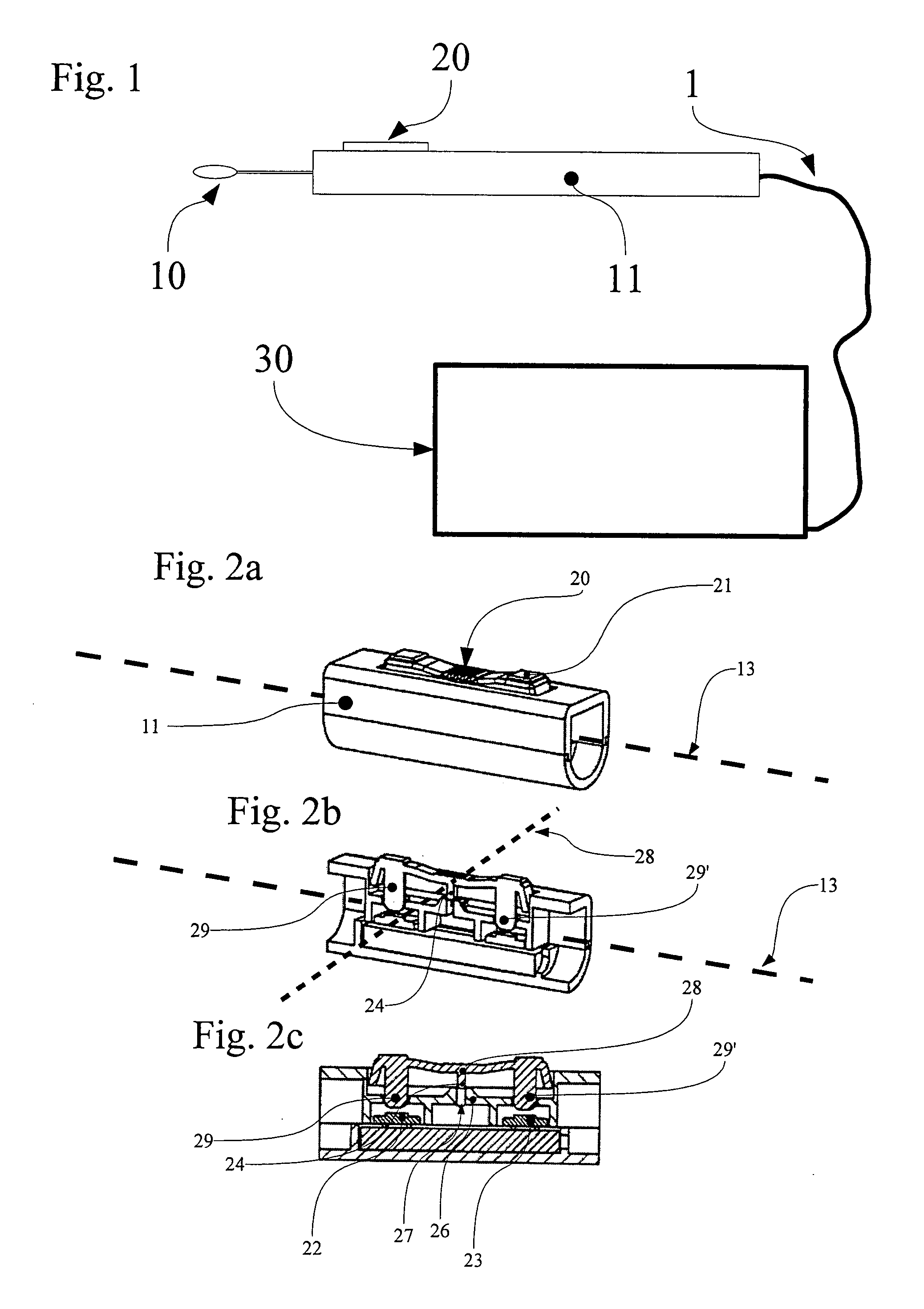
[0026]FIG. 1 shows the most important components of a surgical apparatus. Two main components represented here comprise an instrument 10 with handle 11 and a control unit 30 for controlling the instrument. The two main components are connected to one another by a connecting lead 1. The handle 11 further comprises a switch 20, which is interrogated by the control unit 30 and contributes indirectly to the control of the instrument 10. The control unit 30 has several operating modes, for example a mode for cutting liver tissue and muscle fibres as well as a mode for coagulation. By means of the switch 20 these modes can be selected and executed. The control unit 30 controls the instrument in accordance with the mode that is selected.

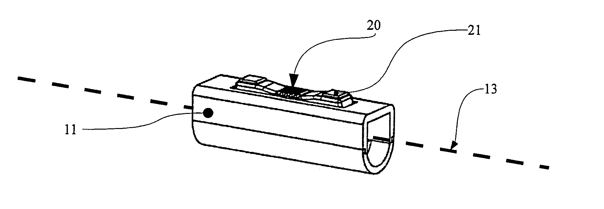
[0027]FIG. 2a shows a switch 20, which is integrated into a handle 11. The oblong operating element 21 of the switch 20 is oriented ...


PUM


Abstract

A surgical apparatus includes an actuation unit disposed on a handle and a control unit providing at least three modes for controlling the electrical instrument. The actuation unit contains a switching rocker with an operating element, which is rotatable about a rocker axis that can be shifted perpendicular to the surface of the handle, so that starting from an initial position a first or second function position can be reached by forwards or backwards rotation about the rocker axis, and a third function position can be reached by pressing the operating element inward, two sensors being disposed on the operating element, one on the left and the other on the right side of the rocker axis, in such a way that by means of the sensors the function position selected by means of the switching rocker can be determined by the control unit.

Description

FIELD OF THE INVENTION[0001]The invention relates to a surgical device, and specifically to an electrosurgical device with a four-position rocker switch.BACKGROUND OF THE INVENTION[0002]In modern surgery a large number of electronic components and electrical devices are employed to ensure that operations are performed reliably and without harm to the patient. For instance, high-frequency surgery has been used for years, in both human and veterinary medicine, in order to coagulate and / or to cut biological tissue. In this procedure high-frequency current is conducted through the tissue that is to be treated or removed, so that owing to protein coagulation and dehydration the tissue is altered or disintegrates. The tissue thus contracts in such a way that the vessels are closed and bleeding is stanched. A subsequent increase in current density causes an explosive vaporization of the tissue fluid and the cell membranes are torn apart, so that the tissue is completely transected. Methods...

Claims


Application Information

Patent Timeline
Patent Type & Authority Applications(United States)
IPC IPC(8): A61B18/00
CPCA61B17/1626A61B18/1402H01H2300/014A61B2018/00958H01H25/008A61B2017/00367
Inventor SCHNITZLER, UWE
Owner ERBE ELEKTROMEDIZIN GMBH
Why Eureka
Try Eureka