Heat shield element for lining a combustion chamber wall, combustion chamber and gas turbine

a technology for combustion chamber walls and heat shield elements, which is applied in the direction of furnaces, lighting and heating apparatus, machines/engines, etc., can solve the problems of crack formation, cracks, and most likely crack formation of support elements or wall structures, and achieves shorter section length, longer relief slots, and greater crack formation risk

Inactive Publication Date: 2009-03-26
SIEMENS AG
View PDF14 Cites 6 Cited by
  • Summary
  • Abstract
  • Description
  • Claims
  • Application Information

AI Technical Summary

Benefits of technology

[0023]Relief slots are preferably provided, which extend from the hot side to the wall side, with the slot length measured along the hot side being greater than the slot length along the wall side. The different in the length of the relief slots along the hot side and along the cold side is required because of the respective temperature gradient. On the hot side, where the risk of crack formation is greater, longer relief slots are particularly effective. On the other hand, on the cooler wall side the mechanical stability and thermal insulation effect of the heat shield element are of primary importance. Therefore a much shorter section length suffices on the cooler wall side. There is also a gradual reduction in slot length in the direction of the temperature drop in this embodiment.
[0024]It is also advantageous that the peripheral side has an end face and a securing face inclined in relation to the end face and having a securing gr

Problems solved by technology

It must be ensured in this process that no hot gas penetrates into the expansion gaps, because otherwise the support elements or wall structure are heated excessively.
The extremely high temperatures at the hot side surface mean t

Method used


Image

  • Heat shield element for lining a combustion chamber wall, combustion chamber and gas turbine
  • Heat shield element for lining a combustion chamber wall, combustion chamber and gas turbine
  • Heat shield element for lining a combustion chamber wall, combustion chamber and gas turbine

Examples


Embodiment Construction

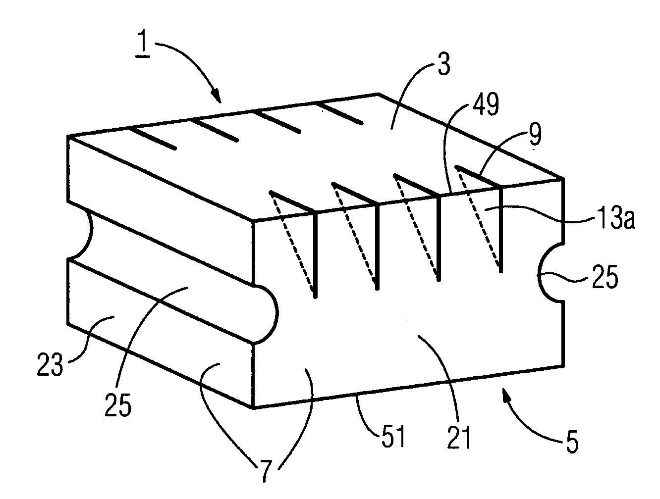
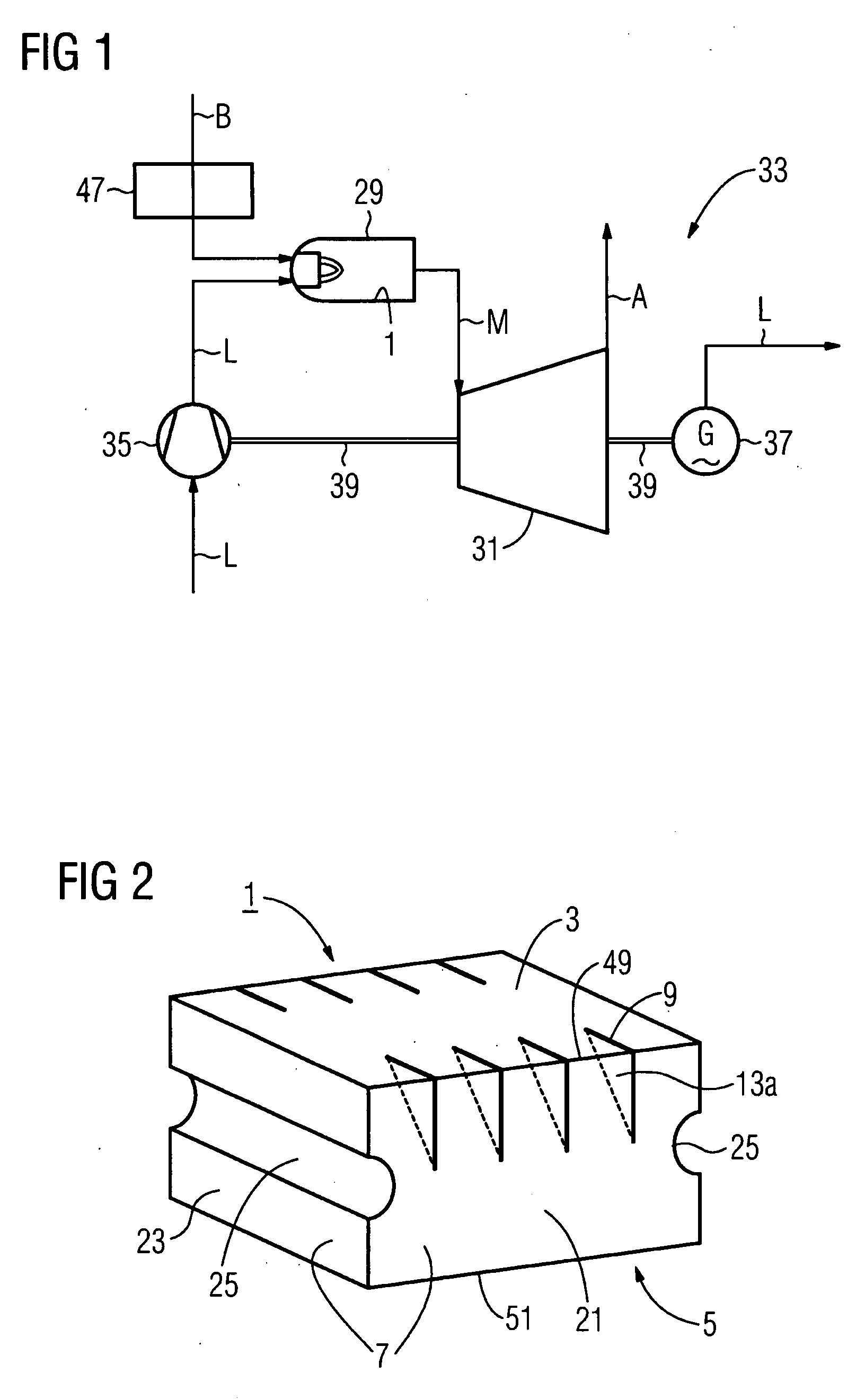
[0034]FIG. 1 shows a schematic diagram of a gas turbine installation 33. It comprises a combustion chamber 29 with a fuel supply system 47 and the air compressor 35, gas turbine 31 and electric generator 37 disposed along one axis 39. Ambient air L is drawn in by the air compressor 35, compressed and then supplied to the combustion chamber 29, where it is mixed with the fuel B and combusted, as a result of which a hot gas M is formed. The combustion chamber 29 is fitted with a heat-resistant combustion chamber lining, formed from a number of heat shield elements 1 disposed adjacent to each other and providing cover. The gas turbine is driven by the hot gas M, which leaves the combustion chamber 29 at high pressure. The hot medium M thereby flows through and drives the gas turbine 31 and escapes as waste gas A. The waste gas A is filtered in a filter system (not shown in detail in this figure) and released into the atmosphere after the filtering process. A generator 37 is coupled to ...


PUM


Abstract

The invention relates to a heat shield element for lining a combustion chamber wall, to a combustion chamber and to a gas turbine. The heat shield element comprises a hot side that can be exposed to a hot medium, a wall side opposite said hot side, and a peripheral side adjoining the hot side and the wall side and having a peripheral side surface. Relief slots are introduced into the material in an area of the heat shield element that is susceptible to material cracks induced by thermal stress, thereby limiting crack propagation.

Description

CROSS REFERENCE TO RELATED APPLICATIONS[0001]This application is the US National Stage of International Application No. PCT / EP2006 / 061625, filed Apr. 18, 2006 and claims the benefit thereof. The International Application claims the benefits of European application No. 05008511.7 filed Apr. 19, 2005, both of the applications are incorporated by reference herein in their entirety.FIELD OF INVENTION[0002]The invention relates to a heat shield block, in particular for lining a combustion chamber wall, with a hot side that can be exposed to a hot medium, a wall side opposite the hot side and a peripheral side adjoining the hot side and the wall side. The invention also relates to a combustion chamber with a combustion chamber wall and to a gas turbine.BACKGROUND OF THE INVENTION[0003]A combustion space with a high level of thermal and / or thermo-mechanical loading such as for example a furnace, a hot gas duct or a combustion chamber in a gas turbine, in which space a hot medium is produce...

Claims


Application Information

Patent Timeline
IPC IPC(8): F23M5/00
CPCF23R3/005F23R2900/00005F27D1/14F27D1/04F27D1/0006
Inventor SCHOLZ, CHRISTIANHEILOS, ANDREASHOFFMANN, STEFAN
Owner SIEMENS AG
Why Eureka
Try Eureka