Drum rotating apparatus for use on construction machines

a construction machine and rotating technology, applied in mechanical devices, electric devices, transportation and packaging, etc., can solve problems such as difficulty in mounting a negative type dry electromagnetic, pollution of the environment, and considerable degradation of the working environment, and achieve the effect of high reliability of the vehicle drive uni

Inactive Publication Date: 2009-03-26
NIHON KENKI CO LTD +1
View PDF16 Cites 30 Cited by
  • Summary
  • Abstract
  • Description
  • Claims
  • Application Information

AI Technical Summary

Benefits of technology

[0023]In case the drum rotating apparatus is applied to a vehicle drive unit of a crawler type vehicle, for example, both of the electric motor and the reduction gear mechanism can be located within the width of a crawler belt, without being projected on the outer side. Therefore, when the crawler type vehicle is traveling on a rough terrain, the electric motor and the reduction gear mechanism can be protected from rocks or other obstacles to guarantee higher reliability of the vehicle drive unit.

Problems solved by technology

Therefore, there has been a serious problem of pollution of environments by exhaust gases emanated from an engine during a drum rotating apparatus is in operation, in addition to a problem that a working environment is degraded to a considerable degree by operational noises of the engine.
However, in the case of an electric motor-driven drum rotating apparatus having lubricant oil within a drum member along with a reducing mechanism, difficulties are encountered in mounting a negative type dry electromagnetic brake on the inner peripheral side of a drum in a compact form, in a complete shielded state from inflammable lubricant oil.

Method used


Image

  • Drum rotating apparatus for use on construction machines
  • Drum rotating apparatus for use on construction machines
  • Drum rotating apparatus for use on construction machines

Examples


Embodiment Construction

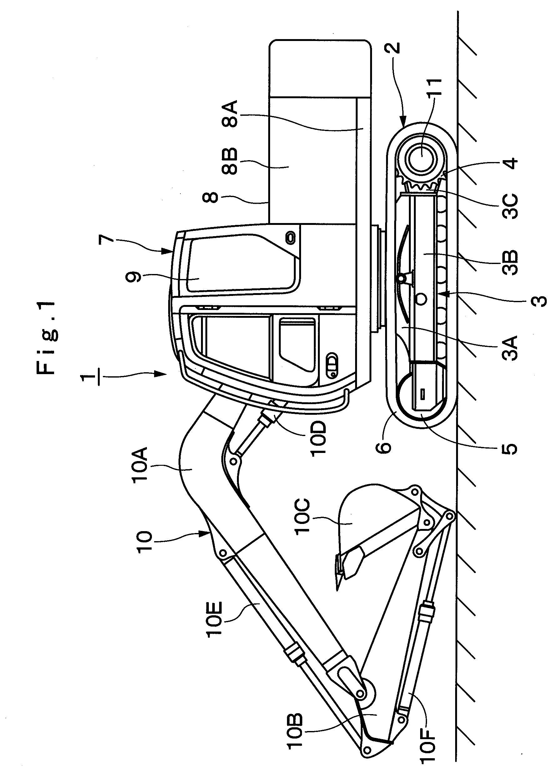
[0033]Hereafter, with reference to FIGS. 1 through 8, the drum rotating apparatus of the construction machine according to the present invention is described more particularly by way of its preferred embodiments applied by way of example to a hydraulic excavator with electric-powered vehicle drive units.

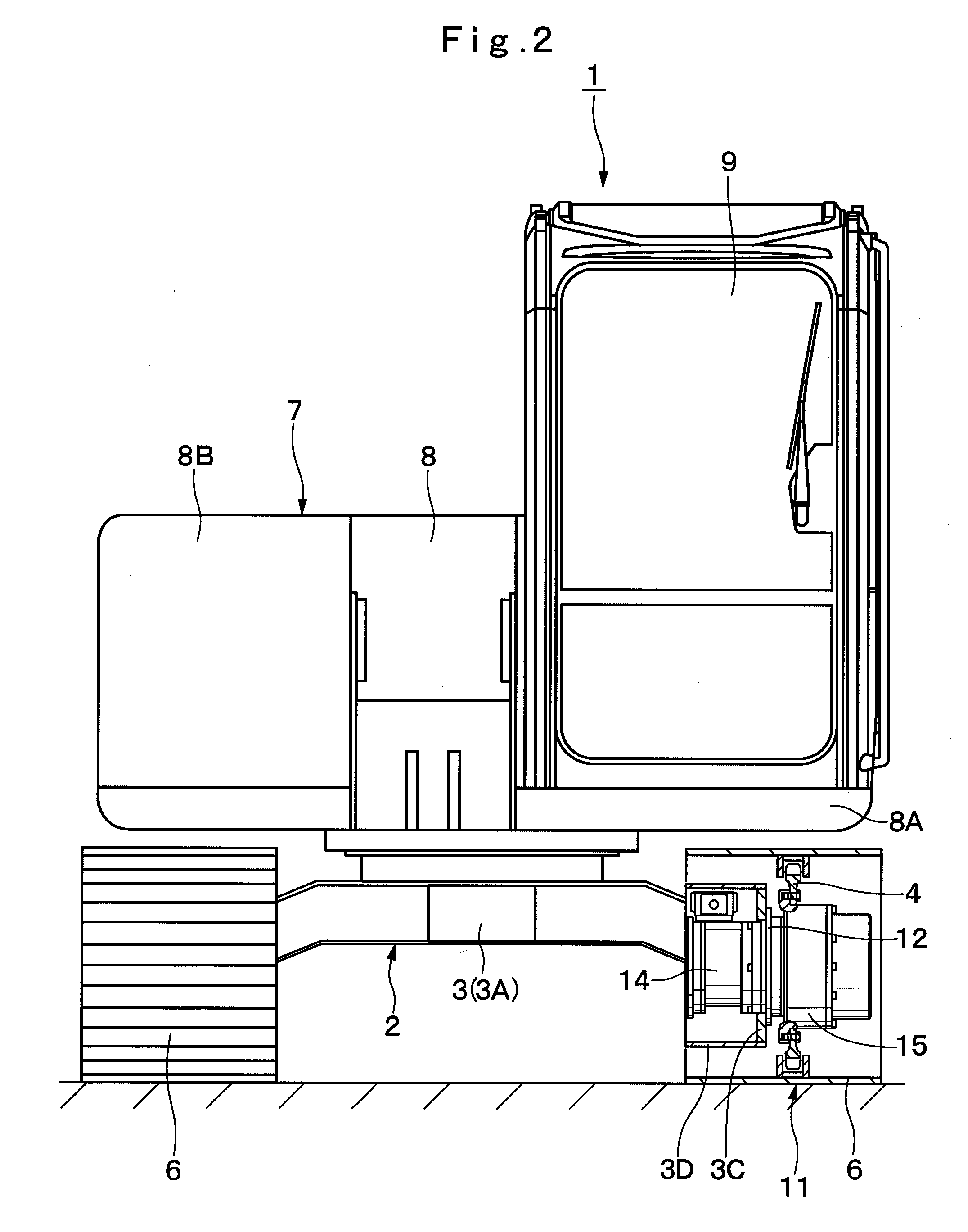
[0034]Referring to FIGS. 1 through 6, there is shown a first embodiment of the present invention. In these figures, indicated at 1 is an electric-motorized hydraulic excavator. This electric-motorized hydraulic excavator 1 is largely constituted by an automotive lower structure 2 and an upper revolving structure 7 which is rotatably mounted on the lower structure 2 which will be described hereinafter.

[0035]In this instance, the lower structure 2 is provided with a truck frame 3 which is composed of a center frame 3A and right and left side frames 3B. The truck frame 3 of this embodiment constitutes a basis of the hydraulic excavator 1. An endless crawler belt 6 is wrapped around a sp...


PUM


Abstract

A support member which is securely fixed to a truck frame is constituted by a tubular body portion and a lid portion. A couple of dry electromagnetic brakes are located in a brake accommodation room within the tubular body portion. The support member is assembled with an electric motor. A drum member which accommodates a planetary reduction gear mechanism is rotatably mounted on the outer periphery of the support member through bearings. A floating seal is provided between the support member and the drum member, and a seal ring (45) is provided between an axial bore in the support member and a coupling shaft. Thus, the two dry electromagnetic brakes are accommodated in the support member, safely shielded from lubricant oil.

Description

TECHNICAL FIELD[0001]This invention relates to a drum rotating apparatus particularly suitable for use in a construction machine, for example, a vehicle drive unit for a hydraulic excavator, a hydraulic crane or a rope winch drum.BACKGROUND ART[0002]Generally, vehicle drive units of construction machines such as hydraulic excavators, wheel loaders and the like employ a drum rotating apparatus for rotating a drum member on which a sprocket is mounted, for driving a crawler belt or for rotating a drum member on which a vehicle wheel is mounted. Also, a drum rotating apparatus is used on a rope winch which is mounted, for example, on a hydraulic crane for winding and unwinding a rope by rotating a drum member (e.g., see, for example, Japanese Patent Laid-Open No. 2000-9017, H1-153840 and S60-183498).[0003]In this instant, the prior art drum rotating apparatuses are largely constituted by a hydraulic motor serving as a drive source, a reducing mechanism which is located on the inner per...

Claims


Application Information

Patent Timeline
Patent Type & Authority Applications(United States)
IPC IPC(8): E02F9/02F16D65/18
CPCB60K7/0007B60K17/046B60K2007/0038B60K2007/0092H02K7/116B62D55/125E02F9/02F16D2121/22H02K7/1025B60Y2200/41B60L2200/40B60L2220/44Y02T10/64B60K7/00F16D55/00
Inventor UZAWA, NOBUOTANAKA, ATSUSHIOCHIAI, MASAMISHIMOZONO, TADAHIROJOJIMA, YOSHIOMIOBATA, TAKESHI
Owner NIHON KENKI CO LTD
Why Eureka
Try Eureka