Method and apparatus for separating particles, cells, molecules and particulates

Inactive Publication Date: 2009-03-26
CHARLES STARK DRAPER LABORATORY +1
View PDF59 Cites 71 Cited by
  • Summary
  • Abstract
  • Description
  • Claims
  • Application Information

AI Technical Summary

Benefits of technology

[0007]In one embodiment, the flow cell can be a removable insert that can be placed into a magnetic housing. In one embodiment,

Problems solved by technology

This limits their usefulness in in-line systems.
Moreover, existing methods typically operate at the macroscale, where diffusi

Method used


Image

  • Method and apparatus for separating particles, cells, molecules and particulates
  • Method and apparatus for separating particles, cells, molecules and particulates
  • Method and apparatus for separating particles, cells, molecules and particulates

Examples


Embodiment Construction

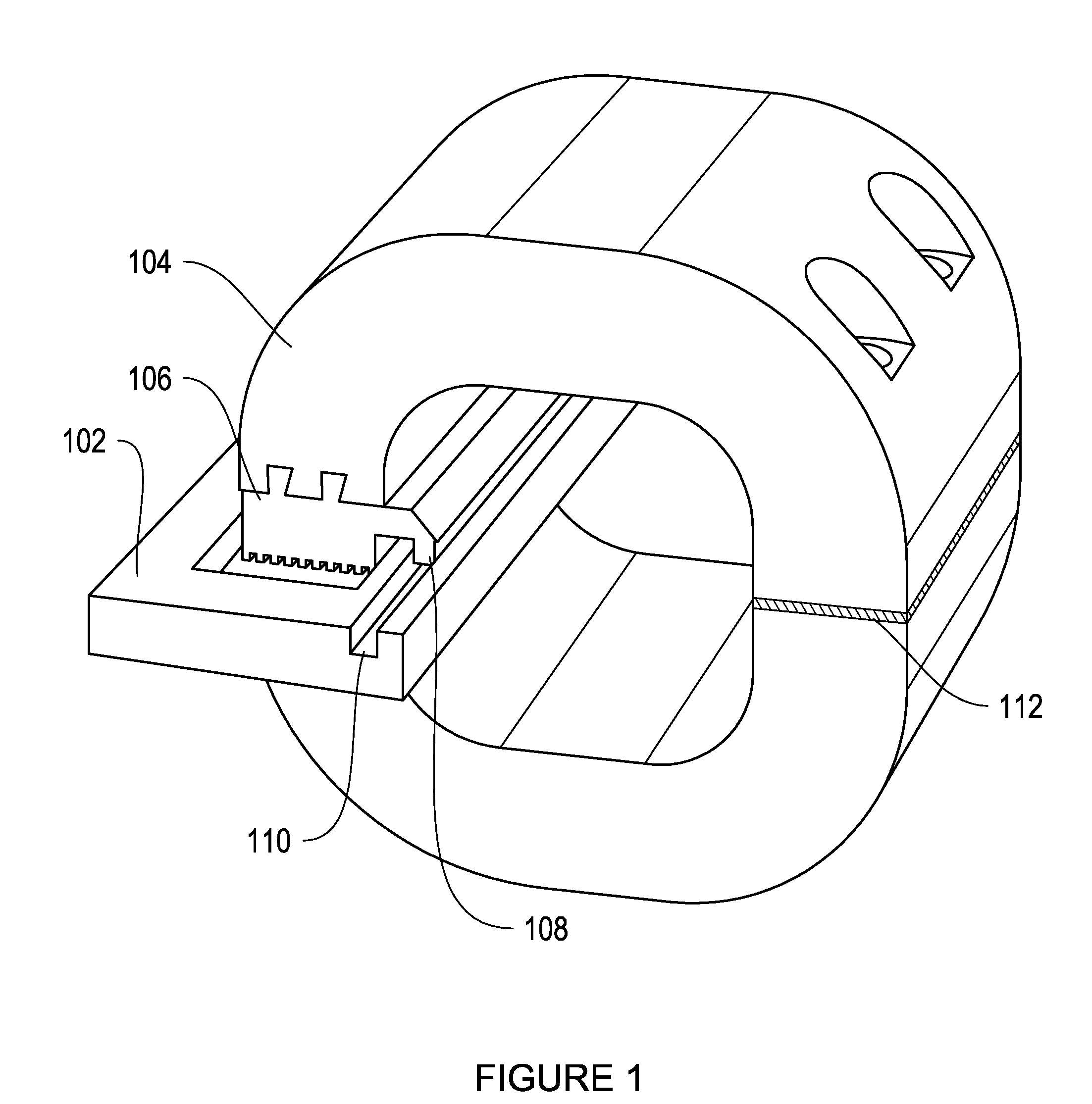
[0028]FIG. 1 is a CAD drawing illustrating one embodiment of a flow cell 102 positioned in a magnetic housing 104. Flow cell 102 is a removable device which is positioned in the magnetic housing 104 by means of a plate 106. Plate 106 can be removable from magnetic housing 104. In some embodiments, magnetic housing 104 may be used with a variety of interchangeable plates. Different plates may have different surface shapes facing flow cell 102. The different surface shapes will result in different magnetic field gradients across the flow cell 102. A particular magnetic field gradient may be desired for a particular application. The desired magnetic field gradient may be selected by selecting a plate with a particular shape. In this embodiment, plate 106 is depicted with a square, ridged surface facing flow cell 102. In other embodiments, the surface of plate 106 may be any of a variety of shapes suited to generate a magnetic field gradient across flow cell 102, such as any of the shap...


PUM


Abstract

A method and apparatus for continuously separating or concentrating particles that includes flowing two fluids in laminar flow through a magnetic field gradient which causes target particles to migrate to a waste fluid stream, and collecting each fluid stream after being flowed through the magnetic field gradient.

Description

CROSS-REFERENCE TO RELATED APPLICATION[0001]This application claims the benefit of U.S. Provisional Application Ser. No. 60 / 925355, filed Apr. 19, 2007, the entire contents of which are incorporated herein by referenceFIELD OF INVENTION[0002]This invention relates to liquid phase separation and / or concentration of particles, cells, or particles in solution. In particular, it relates to separation or concentration from flowing liquids. It provides a means to simply and rapidly extract target objects from complex mixtures. Such devices are useful in systems for, e.g., medical therapy (similar to dialysis), but also for detection, purification, and synthesis. A specific embodiment is in the magnetic separation of pathogens from infected blood.BACKGROUND OF THE INVENTION[0003]Chemical and biological separation and concentration has historically included methods such as solid-phase extraction, filtration chromatography, flow cytometry and others. Known methods of magnetic separation in b...

Claims


Application Information

Patent Timeline
IPC IPC(8): B07C5/344
CPCB03C1/0332Y10T436/2575B03C2201/26B03C2201/18
Inventor VARGHESE, MATHEWFIERING, JASON O.INGBER, DONALD E.XIA, NANMESCHER, MARK J.BORENSTEIN, JEFFREY T.YUNG, CHONG WING
Owner CHARLES STARK DRAPER LABORATORY
Why Eureka
Try Eureka