Multipole coils

a multi-coil, multi-coil technology, applied in the direction of coils, electromagnets, magnetic discharge control, etc., can solve the problems of large space, inability to precisely reproduce the manufacturing process, and deviations cannot be prevented, so as to improve heat dissipation, increase current, and improve heat dissipation

Inactive Publication Date: 2009-03-26
CEOS CORRECTED ELECTRON
View PDF6 Cites 10 Cited by
  • Summary
  • Abstract
  • Description
  • Claims
  • Application Information

AI Technical Summary

Benefits of technology

[0017]Another advantage is the improved heat dissipation, since gaps containing air form between the wires during production of the windings. Heat dissipation is improved by exactly disposing the printed circuit boards on top of each other.
[0018]In addition to increasing the current, the fields generated by the coils can also be reinforced by generating several windings per coil through spiral arrangement or through several printed circuit board layers generated during rolling. A combination of both is naturally also possible, which provides excellent field generation efficiency. When several layers are provided, measures must be taken to position the windings that interact as coils, or the spiral arrangements of windings with great precision with respect to each other.
[0019]The windings of the coils of the different printed circuit board layers suitably extend in such a fashion that the winding centers are always disposed on radii in a plane that extends perpendicularly to the axis. This widens the window formed by the coil windings, from the inside to the outside in correspondence with the increasing radius. A hexapole comprises six coils, which provides e.g. an opening angle of approximately 60° each with respect to the axis. This coil design cannot be realized with conventional technology. It is advantageous in that fields of considerably higher correctness of the different multipoles can be generated, since the separation between individual coils can be minimized. This is important, in particular, for a large number of poles. Moreover, reproduction of the generated fields is considerably facilitated through the exact positioning of the windings.
[0020]The coils are thereby preferentially designed to form substantially rectangular windows, wherein the long sides of the windows suitably extend in the axial direction and the short sides in the radial direction, thereby generating more effective fields.
[0021]When the windings are spirally arranged in several printed circuit board layers, the outer spiral arrangements suitably comprise more windings than the inner ones. This can be realized on the one hand by providing more space in this area, which is advantageous in that with increasing distance from the axis, the field excitation increases, such that a homogeneous field of maximum strength is provided in the area of the axis. The above-mentioned winding centers are thereby located in the center of the neighboring strip conductors of the spiral arrangement to also enable the above-mentioned outward window enlargement with respect thereto. The field excitation which is stronger to the outside, could naturally also be realized using larger conductor cross-sections and larger current loads, which would, however, generally require separate current supply lines.
[0022]Field excitation can be further improved by doubling the number of windings per printed circuit board layer by providing the front and rear sides of the printed circuit board with strip conductors that form windings. Of course, the strip conductors of the printed circuit board layers must then be separated by an insulating layer.

Problems solved by technology

Multipoles of this type require a large amount of space, comprise fields which are ineffective with respect to the area of the axis due to the large distance from the axis, and cannot be manufactured in an exactly reproducible fashion, since deviations cannot be prevented during winding of the wires both manually as well as mechanically.

Method used


Image

  • Multipole coils
  • Multipole coils
  • Multipole coils

Examples


Embodiment Construction

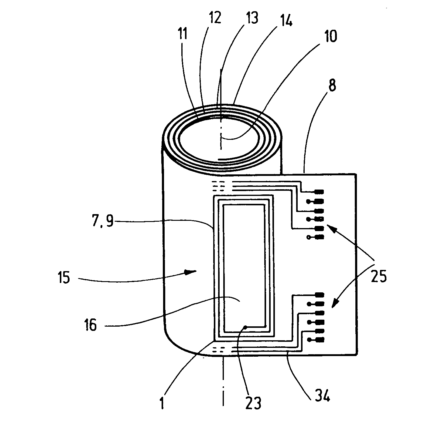
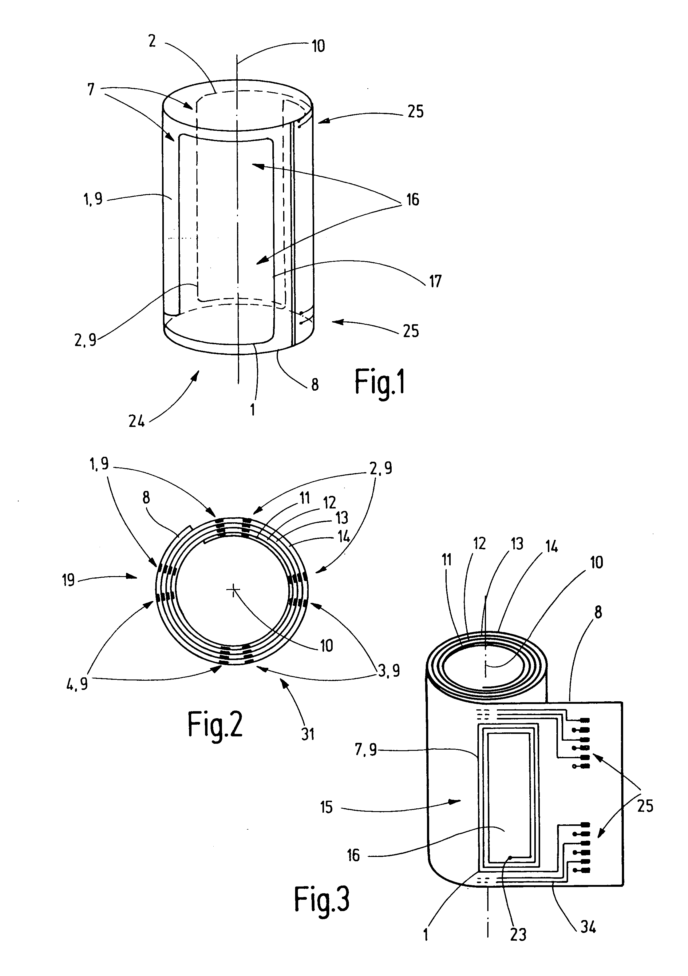
[0051]FIG. 1 shows a simple embodiment of the invention in order to explain the basic principle. Two coils 1 and 2, which each consist of one winding 7, are disposed on a printed circuit board 8 for generating a dipole 24. Each winding 7 is disposed on the printed circuit board 8 in the form of a strip conductor 9, and is loaded with current via connections 25. The windings 7 form rectangular windows 16 with rounded edges, wherein the long sides 17 of the windows 16 are oriented along an imaginary axis 10. The axis 10 is the optical axis when the multipole coils are used in the field of particle optics. The printed circuit board 8 is made from a flexible material and rolled into a cylinder which is hollow inside, such than the two coils 1, 2 concentrically enclose the axis 10.

[0052]FIG. 2 shows a sectional view of one embodiment, in which the printed circuit board 8 is rolled in several printed circuit board layers 11, 12, 13, 14. These multipole coils 1, 2, 3, 4 form a quadrupole 3...


PUM

PropertyMeasurementUnit
outer diameteraaaaaaaaaa
diameteraaaaaaaaaa

Abstract

Multipole coils (1, 2, 3, 4, 5, 6) comprise at least two coils (1, 2) which are disposed to concentrically enclose an imaginary axis (10). Multipole coils (1, 2, 3, 4, 5, 6) of this type are designed in such a fashion that effective fields can be generated in the area of an imaginary axis (10) when little installation space is available, and the multipole coils can be reproducibly manufactured with high precision. This is achieved in that, for each coil (1, 2, 3, 4, 5, 6), at least one winding (7) is disposed on a flexible printed circuit board (8) through disposed strip conductors (9), and the printed circuit board (8) is rolled in at least one printed circuit board layer (11, 12, 13, 14).

Description

[0001]This application claims Paris Convention priority of DE 10 2007 045 874.8 filed Sep. 25, 2007 the complete disclosure of which is hereby incorporated by reference.BACKGROUND OF THE INVENTION[0002]The invention concerns multipole coils comprising at least two coils which are disposed to concentrically enclose an imaginary axis. Multipole coils of this type are used to generate magnetic fields which are disposed concentrically about an imaginary axis. A dipole, a quadrupole, a hexapole, an octupole etc. can e.g. be formed in this fashion.[0003]The main field of application is the influence of particle beams, i.e. ion or electron beams in particle optics. Since 1947, when O. Scherzer showed that the optical path of electron lenses can be corrected by non-rotationally symmetrical lenses (O. Scherzer: “Sphärische und chromatische Korrektur von Elektronen-Linsen” (spherical and chromatic correction of electron lenses), OPTIK, DE, JENA, 1947, pages 114-132, XP002090897, ISSN: 0863-02...

Claims


Application Information

Patent Timeline
Patent Type & Authority Applications(United States)
IPC IPC(8): H01F5/00H01F7/06H01F7/127
CPCH01F5/003H01J29/762H01J29/768H01J37/153Y10T29/4902H01J2237/141H05K1/0393H05K1/165H01J37/26H01J1/50
Inventor ZACH, JOACHIMKALLENBACH, MATTHIAS
Owner CEOS CORRECTED ELECTRON
Why Eureka
Try Eureka