Signal Generating Apparatus and Signal Generation Method

a signal generation and signal technology, applied in multiplex communication, orthogonal multiplex, data switching networks, etc., can solve the problems of disadvantageous degradation of the receiving characteristic of such a multi-carrier signal, transmission power directly affecting the broadness of coverage, and maximum transmission power

Active Publication Date: 2009-03-26
NEC CORP
View PDF7 Cites 24 Cited by
  • Summary
  • Abstract
  • Description
  • Claims
  • Application Information

AI Technical Summary

Benefits of technology

[0011]An object of the present invention is to provide a signal generating apparatus capable of reducing, in correspondence with the number of subcarriers used, processing to generate a transmission signal in which PAR has been reduced in the case of multiplexing data symbols with respect to E subcarriers which are sufficiently less as compared to the number F of points of inverse Fourier transform as in the case of OFDMA.
[0012]Another object of the present invention is to provide a signal generation method capable of reducing, in correspondence with the number of subcarriers used, processing to generate a transmission signal in which PAR has been reduced in the case of multiplexing data symbols with respect to E subcarriers which are sufficiently less as compared to the number F of points of inverse Fourier transform as in the case of OFDMA.

Problems solved by technology

A multicarrier signal with a high PAR is greatly distorted by an amplifier with the non-linear input / output relationship in transmitting such a multicarrier signal so that receiving characteristic in receiving such a multicarrier signal is disadvantageously deteriorated.
However, when an input back-off is enlarged, the maximum transmission power is limited and the limitation of the transmission power directly affects broadness of coverage.

Method used


Image

  • Signal Generating Apparatus and Signal Generation Method
  • Signal Generating Apparatus and Signal Generation Method
  • Signal Generating Apparatus and Signal Generation Method

Examples


first exemplary embodiment

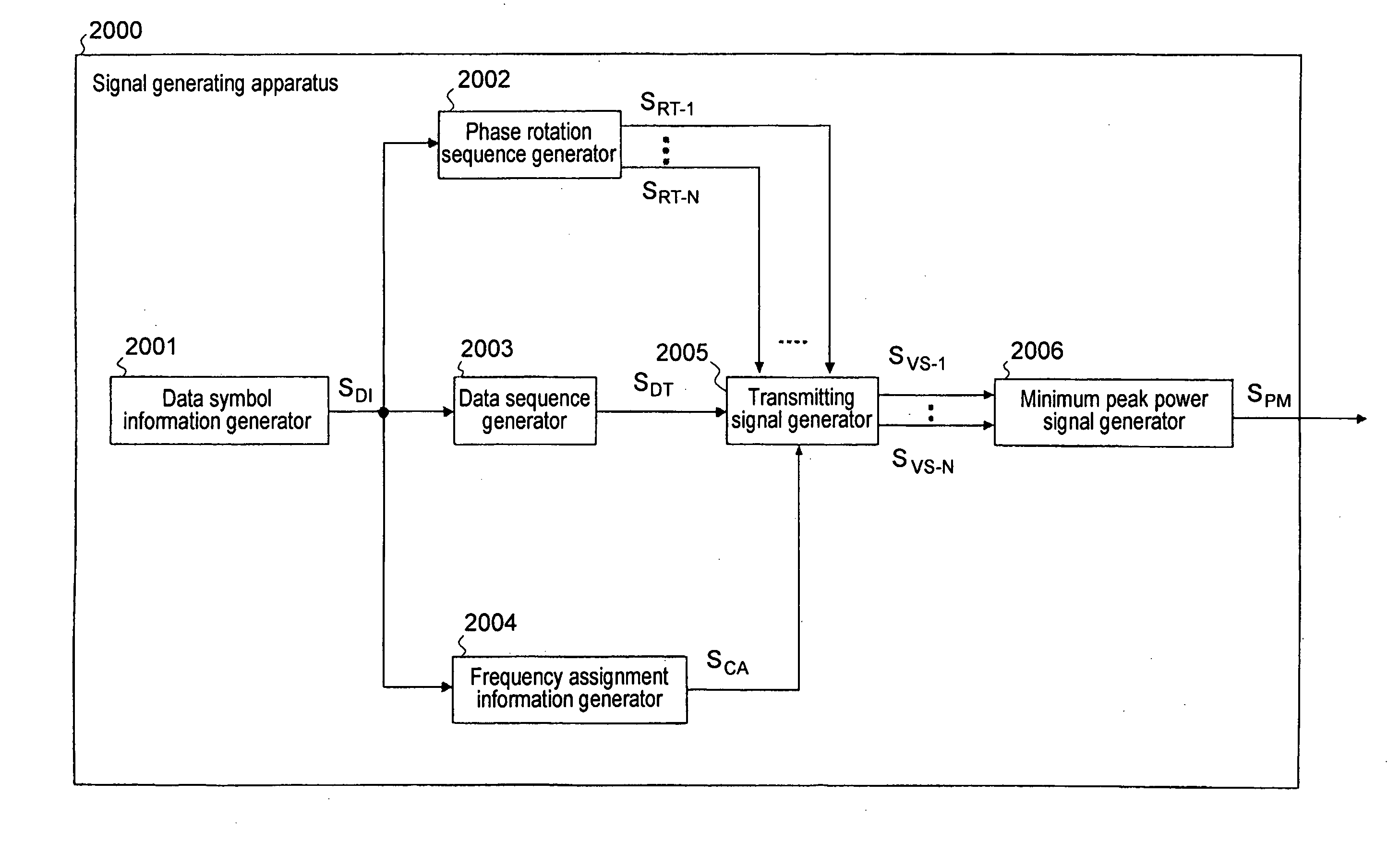
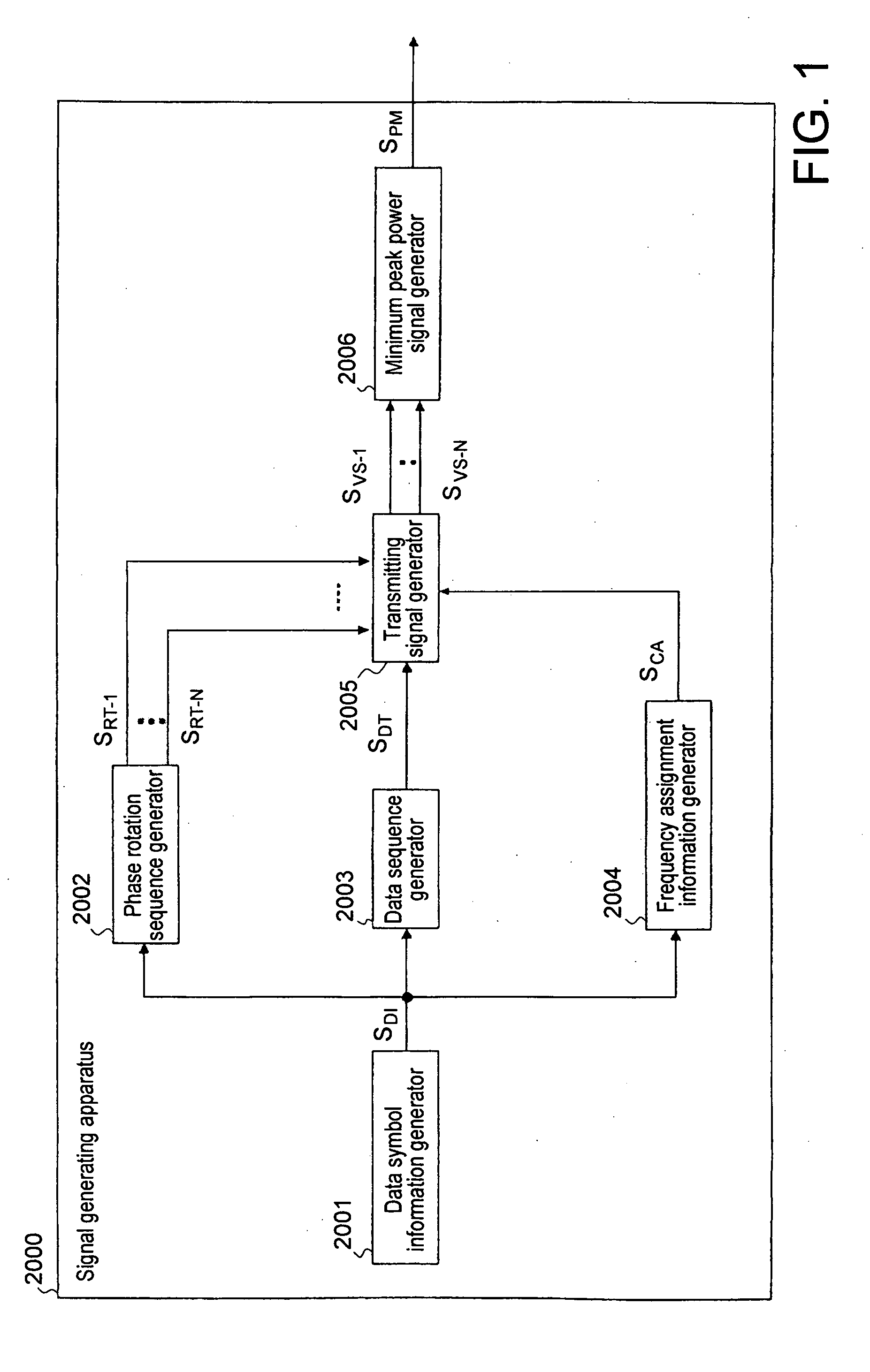
[0057]As shown in FIG. 3, signal generating apparatus 1000 according to the first exemplary embodiment of the present invention includes: data symbol information generator 1001 supplied with a data symbol to be transmitted to generate data symbol information SDI; phase rotation sequence generator 1002 for generating N phase rotation sequence SRT-1 to SRT-N on the basis of data symbol information SDI; data sequence generator 1003 for generating data symbol sequence SDT on the basis of the data symbol information SDI; frequency assignment information generator 1004 for generating frequency assignment information SCA on the basis of data symbol information SDI; rotation sequence selection signal generator 1005 for generating N rotation sequence selection signals SRS-1 to SRS-N on the basis of N phase rotation sequences SRT-1 to SRT-N and frequency assignment information SCA; and a minimum peak power signal generator 1006 for outputting minimum peak power signal SPM on the basis of N ph...

second exemplary embodiment

[0071]The signal generating apparatus of the second exemplary embodiment of the present invention is such that the configuration of the rotation sequence selection signal generator in the signal generating apparatus of the first exemplary embodiment shown in FIG. 3 is changed, and other parts are similar to those of the first exemplary embodiment. FIG. 9 shows rotation sequence selection signal generator 1500 used in the second exemplary embodiment.

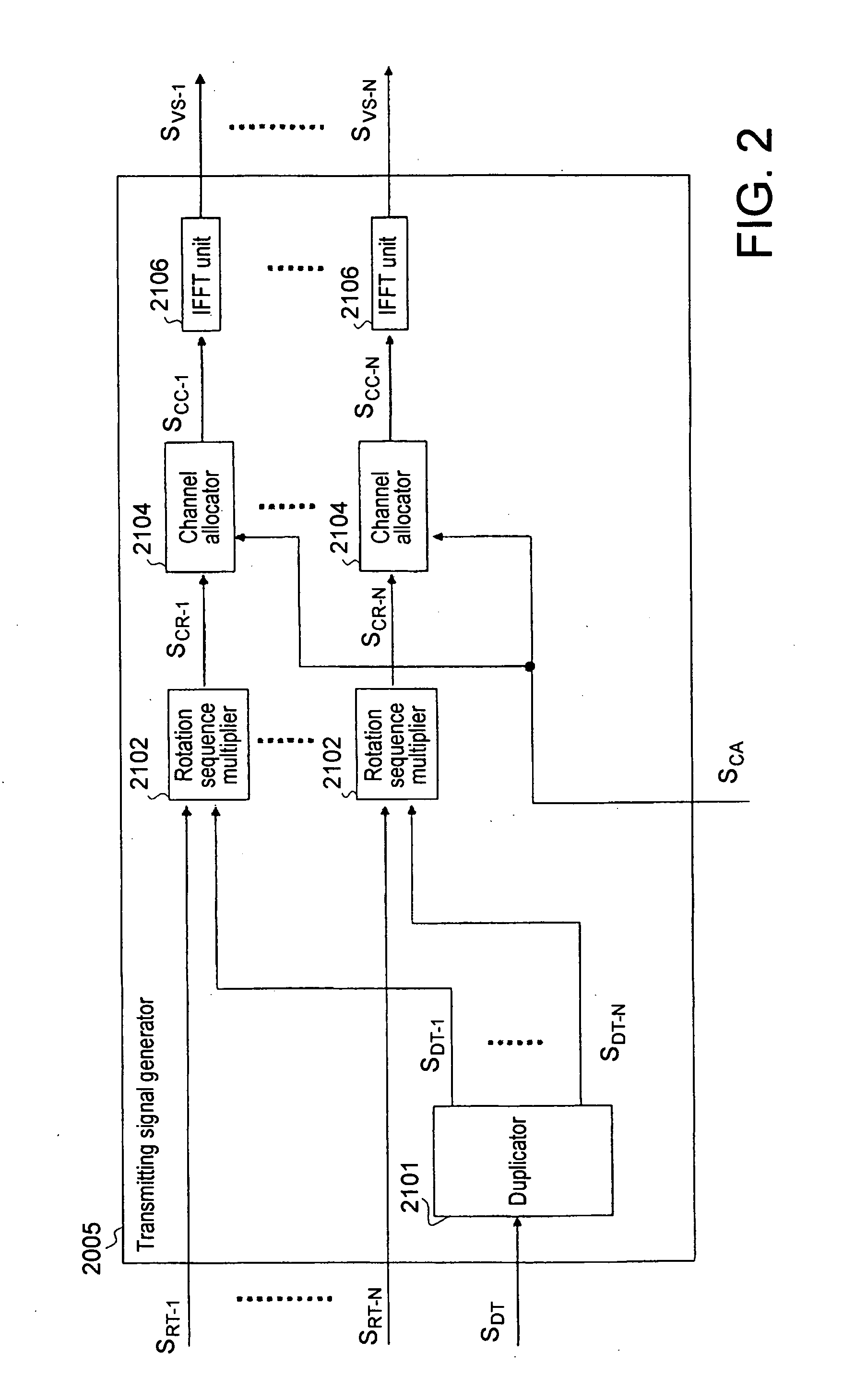
[0072]Rotation sequence selection signal generator 1500 used in the second exemplary embodiment includes: as shown in FIG. 9, duplicator 1101 for duplicating data symbol sequence SDT to output N data symbol sequences SDT-1 to SDT-N; N pieces of rotation sequence multipliers 1102 for multiplying data symbol sequences SDT-1 to SDT-N and phase rotation sequences SRT-1 to SRT-N corresponding thereto to output phase multiplication data sequences SRM-1 to SRM-N; subgroup channel information generator 1104 for generating subgroup channel informa...

third exemplary embodiment

[0078]The signal generating apparatus of the third exemplary embodiment of the present invention is similar to the signal generating apparatuses of the above-described first and second exemplary embodiments as the apparatus configuration, but differs from the cases of the first and second exemplary embodiments in connection with the configuration of subgroup that subgroup channel information SSG generated at the subgroup channel information generator indicates. FIG. 11 is a diagram for explaining the configuration of subgroup used in the third exemplary embodiment, and shows the configuration of subgroup which is indicated by subgroup channel information SSG that subgroup channel information generator 1104 generates.

[0079]In the third exemplary embodiment, it is assumed that Q and R are natural numbers to satisfy the relation expressed as Q×R=M, when subgroup channel information generator 1104 receives frequency assignment information SCA as an input, it outputs, as subgroup channel...


PUM


Abstract

A signal generating apparatus, which is adapted for outputting a multicarrier signal where data are multiplexed with respect to a plurality of subcarriers, includes: a rotation sequence selection signal generator for generating a plurality of rotation sequence selection signal sequences which vary the phase relationship between subcarriers on the basis of a plurality of phase rotation sequences and include the number of samples, which are smaller than that of actual transmission signals; and a minimum peak power signal generator for selecting a signal of which peak power becomes minimum from the plurality of rotation sequence selection signals to generate an actual transmission signal by using a phase rotation sequence multiplied with respect to the selected signal.

Description

TECHNICAL FIELD[0001]The present invention relates to a signal generating apparatus and a signal generation method for generating a multicarrier signal in which data are multiplexed with respect to a plurality of subcarriers, and more particularly to a signal generating apparatus and a signal generation method for generating a multicarrier signal of which peak power has been reduced.BACKGROUND ART[0002]In a multicarrier transmission system of multiplexing data symbols with respect to a plurality of subcarriers as in the OFDMA (Orthogonal Frequency Division Multiple Access) to simultaneously transmit a plurality of carriers corresponding to respective subcarriers, the plurality of carriers are caused to be of the same phase so that a high power peak takes place. As a result, PAR (Peak to Average power Ratio) becomes large.[0003]A multicarrier signal with a high PAR is greatly distorted by an amplifier with the non-linear input / output relationship in transmitting such a multicarrier s...

Claims


Application Information

Patent Timeline
Patent Type & Authority Applications(United States)
IPC IPC(8): H04L12/413
CPCH04L27/2621
Inventor KOYANAGI, KENJI
Owner NEC CORP
Why Eureka
Try Eureka