
Disposable flexible endoscope

a flexible, endoscope technology, applied in the field of disposable flexible endoscopes, can solve the problems of inability to adapt to the needs of different users, inability to adjust the cleaning speed, so as to achieve the effect of reducing the cost of the uni

Inactive Publication Date: 2009-03-26
SINGLE USE SURGICAL
View PDF7 Cites 54 Cited by
  • Summary
  • Abstract
  • Description
  • Claims
  • Application Information

AI Technical Summary

Benefits of technology

[0017]Moreover, the control unit does nothing more than transmit electrical signals to and from the computer, as well as providing connections to any such aspiration and irrigation sources. Thus the disposable section of the system, namely the endoscope itself, is relatively low cost, not including any optic fibres or connection interface therefor.
[0021]The endoscope is preferably manufactured mainly from plastic materials to minimise unit cost, together with optical and electronic components to capture and transmit the image and provide illumination. The mechanics are based on well established principles from reusable endoscopes however mass production and automotive techniques are used to control costs.

Problems solved by technology

The geometry of the instruments, particularly the fine lumens and valves, makes this difficult and time consuming.
Some of the cleaning has been semi automated using flushing cycles, but most of the initial cleaning is still done manually with brushes and can be subject to variability.
The unit procedure cost for reusable endoscopes depends on their frequency of use, capital cost and their maintenance and decontamination costs.
A further cost associated with reusable endoscopes is their integration with a control unit that is employed to display, and enable manipulation of, the image transmitted from the distal end.
These necessarily imply reliable connection interfaces with the control unit, adding to the cost of the endoscope system.

Method used


Image

  • Disposable flexible endoscope
  • Disposable flexible endoscope
  • Disposable flexible endoscope

Examples


Embodiment Construction

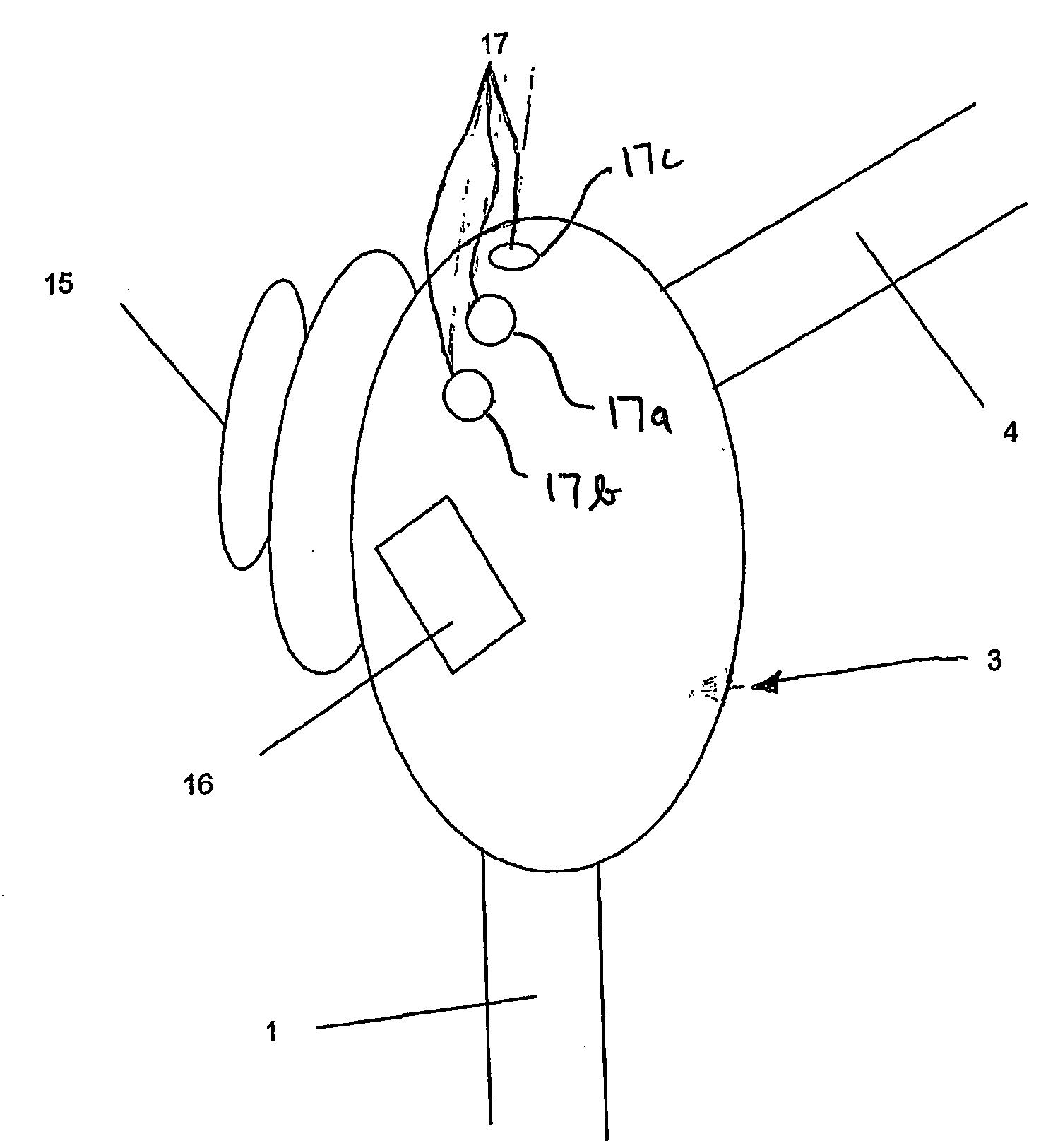
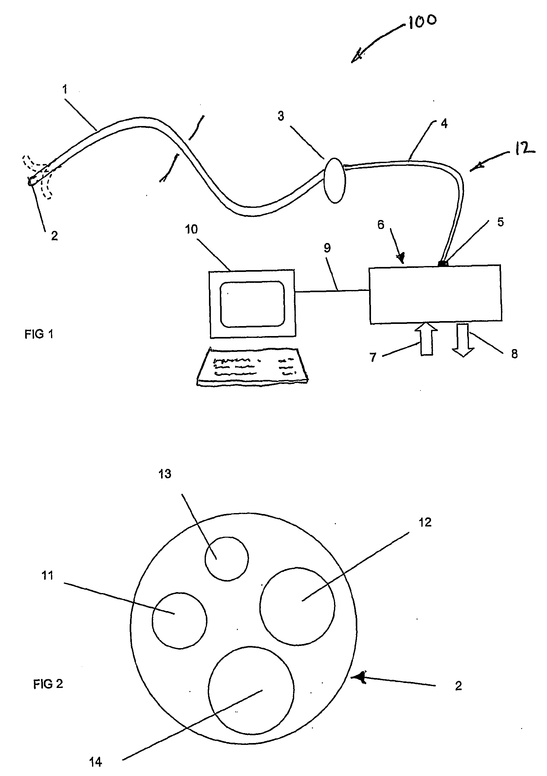
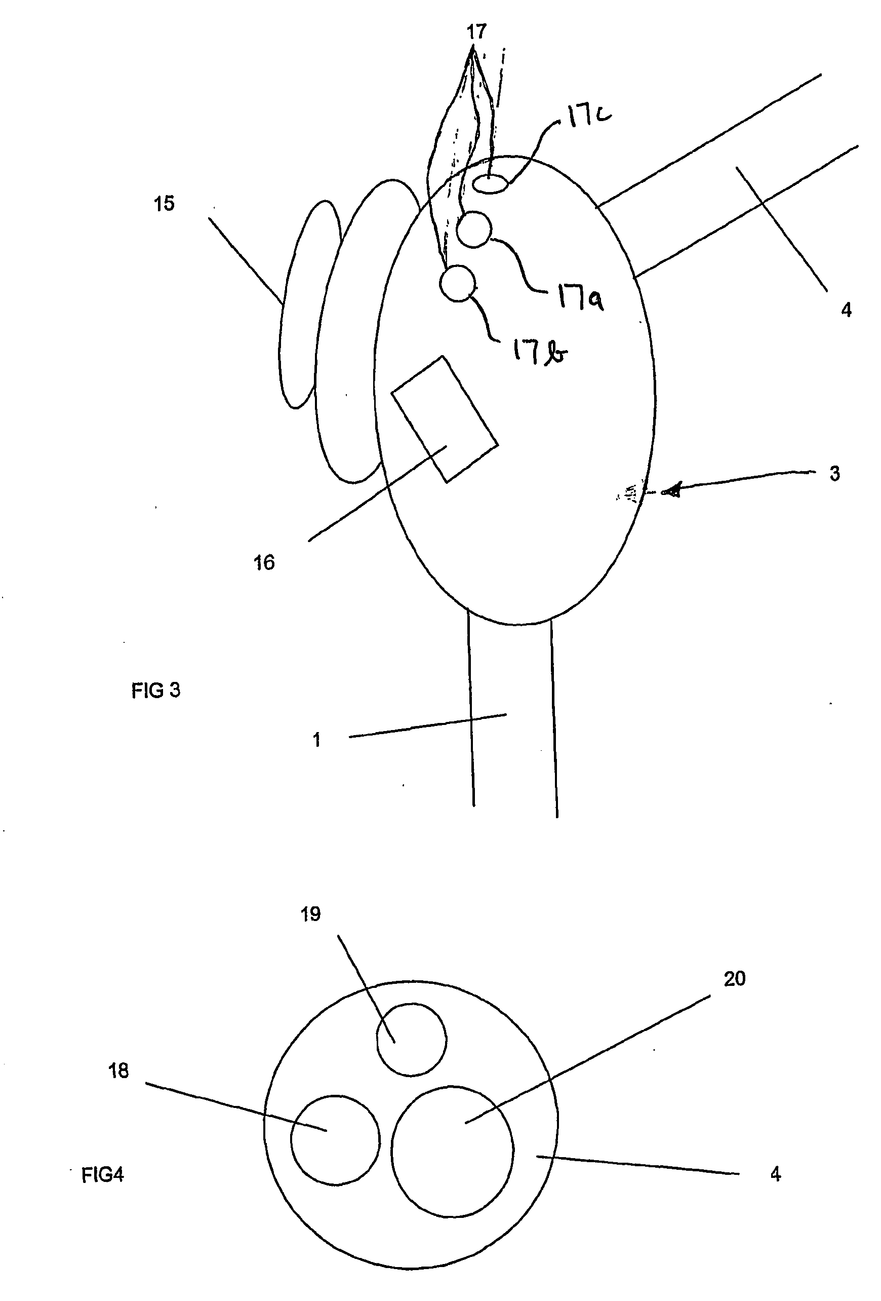
[0027]As shown in FIG. 1, an endoscope system 100 comprises a disposable endoscope 12 connected to a reusable control unit 6. The endoscope 12 consists of a flexible insertion section 1 connected to an operating handle 3, which itself connects to an umbilical cord 4. A connection interface 5 at the end of the umbilical 4 is the final component of the disposable endoscope 12.

[0028]The connection interface 5 links the endoscope to the control unit 6, which itself is linked to an image display and control personal computer 10 by cable 9.

[0029]The control unit 6 is connected to a supply of irrigation fluid 7 and aspiration 8. This allows fluids (e.g. water, air) to be admitted into the endoscope, and controls suction from it.

[0030]As shown in FIG. 2, the distal end of the insertion section contains an illumination source 11, a video camera with optics 12, an irrigation channel 13 and a channel 14 for suction or for instruments (not shown). All of the insertion tube is flexible, to allow...


PUM


Abstract

A disposable endoscope system (100) connects to a reusable control and monitor unit 6,10 and comprises a flexible insertion section (1) connected to an operating handle (3) that connects to an umbilical cord (4). The end interface (5) of the umbilical is the final component of the disposable endoscope. The flexible insertion section (2) has a video camera (12), an illumination source (11) and an actively steered section that is controlled from the operating handle. The endoscope provides PC mouse functionality, enabling image and procedure logging and controls and integration with other patient management systems.

Description

BACKGROUND[0001]Endoscopes have been used since the 1960's to view celiac cavities of a patient's body. They are long, slender instruments having a flexible shaft with an objective lens at the distal end and an image transmission system to transmit the image to one or more viewers. Endoscopes are also equipped with an illumination system either at the distal end, or transmitted to the distal end. Flexible endoscopes have a means of directing the distal tip remotely from an operating handle so that the endoscope can be navigated through the body. They also have one or more channels through which air, water or aspiration can be directed as well as instruments. This allows both diagnosis of the patient and therapy, including tissue sampling, injection, electrosurgery and other clinical activities.[0002]Traditionally, endoscopes have been manufactured as reusable instruments and so have to be decontaminated between patients to avoid cross infections. The geometry of the instruments, par...

Claims


Application Information

Patent Timeline
Patent Type & Authority Applications(United States)
IPC IPC(8): A61B1/06H04N7/18A61B1/005A61B1/05
CPCA61B1/00103A61B1/05A61B1/0051A61B1/00105H04N7/183
Inventor TULLEY, MATTHEW
Owner SINGLE USE SURGICAL
Learn More