Substrate manufacturing method

Inactive Publication Date: 2009-04-02
SAMSUNG ELECTRO MECHANICS CO LTD
View PDF6 Cites 6 Cited by
  • Summary
  • Abstract
  • Description
  • Claims
  • Application Information

AI Technical Summary

Benefits of technology

[0008]An aspect of the invention is to provide a substrate manufacturing

Problems solved by technology

According to prior substrate manufacturing methods, substrate does not provide enough stiffness for manufacturing processes without a core

Method used


Image

  • Substrate manufacturing method
  • Substrate manufacturing method
  • Substrate manufacturing method

Examples


second embodiment

[0072]FIG. 14 to 17 illustrate processes of a substrate manufacturing method according to the invention. In FIG. 14 to 17, are illustrated, a carrier 300, an etching protection film 310, a transfer pattern 322, a nickel layer 324, a gold layer 326, a circuit stack body 330, an insulation layer 332, a circuit pattern 334 and an inner via 336.

[0073]The second embodiment of the invention may be fulfilled in similar flow chart to that of the first embodiment. In this embodiment, forming the circuit stack body 330 on the adhesion layer 220 is accomplished by burying a circuit into the adhesion layer 220.

[0074]FIG. 14 illustrates forming the transfer pattern 322 on the carrier 300. In this embodiment, the carrier 300 is a metal plate, on which the etching protection film 310 is formed. The etching protection film 310 may be composed of metal like nickel etc.

[0075]The transfer pattern 322 is a circuit formed on the etching protection film 310. On a surface of the transfer pattern 322, the ...

first embodiment

[0076]In FIG. 15 to 17, the transfer pattern 322 is buried into the adhesion layer 220, on which the insulation layer 332, the circuit pattern 334 and the inner via 336 is formed to form the circuit stack body 330. For forming the circuit stack body 330, similar process noted in the first embodiment may be used. The circuit pattern 334 may be buried into the insulation layer 332 by similar process to burying the transfer pattern 322 into the adhesion layer 220.

[0077]The circuit stack body 330 may be separated from the support body 200 by fulfilling a routing process according to the dashed dotted line in FIG. 16. Detail description about this is similar to the description about FIG. 6 and FIG. 7 on the first embodiment of the invention.

[0078]FIG. 17 illustrates the circuit stack unit 340 separated from the support body 200. The circuit stack unit 340 comprises the circuit stack body 330, the adhesion layer 220 and the second separation layer 214. An electrode may be formed with the ...

third embodiment

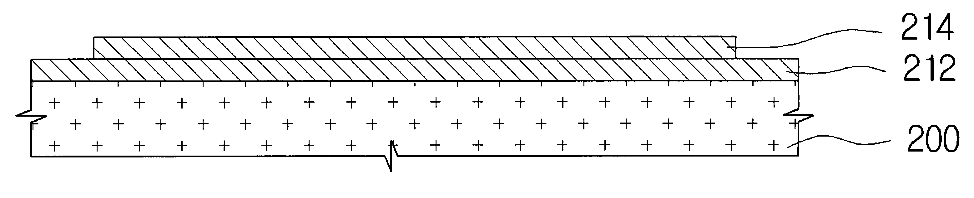
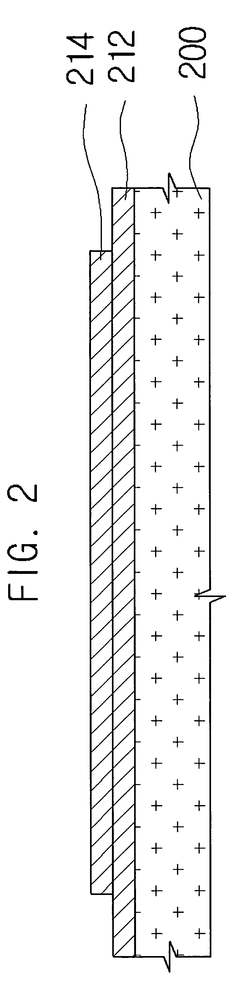
[0081]FIG. 18 illustrates a support body and support layers for a substrate manufacturing method according to the invention. In FIG. 18, are illustrated, a support body 200, a first separation layer 212, a second separation layer 218, and an adhesion layer 220.

[0082]In the first embodiment of the invention, the second separation layer 214 is a copper film. The second separation layer 218 may be formed of insulation material.

[0083]In this embodiment, The support body 200 and the first separation layer 212 may be provided by a copper clad laminate. The second separation layer 218 may be provided by coating silicon on the first separation layer 212.

[0084]In this embodiment, a patterned mask may be required to form a silicon coating to pre-determined shape, because the second separation layer 218 covers part of the first separation layer 212.

[0085]The adhesion layer 220 is formed to cover the first and the second separation layer 212, 218. Subsequent process for substrate manufacturing ...


PUM

PropertyMeasurementUnit
Compositionaaaaaaaaaa
Adhesion strengthaaaaaaaaaa
Electrical conductoraaaaaaaaaa

Abstract

A substrate manufacturing method is disclosed. A substrate manufacturing method, comprising: providing a support body on which a first separation layer is formed; forming a second separation layer on the first separation layer; forming an adhesion layer which covers the first separation layer and the second separation layer; forming a circuit stack body on the adhesion layer; cutting the circuit stack body, the adhesion layer and the second separation layer to a pre-determined shape; and forming a circuit stack unit by separating the second layer from the first layer, provides easy separation of the circuit stack pattern, which formed on the support body, from the support body and reduced manufacturing cost by reducing number of process and required materials for manufacturing coreless thin substrate.

Description

CROSS-REFERENCE TO RELATED APPLICATIONS[0001]This application claims the benefit of Korean Patent Application No. 10-2007-0098387 filed with the Korean Intellectual Property Office on Sep. 28, 2007, the disclosure of which is incorporated herein by reference in its entirety.BACKGROUND[0002]1. Technical Field[0003]The present invention relates to a substrate manufacturing method.[0004]2. Description of the Related Art[0005]The size of electronic component for electronic devices gets smaller. Accordingly, the size of package of a device chip also gets smaller. This requires thinner substrates for the package.[0006]Meanwhile, to minimize the loop inductance originated by physical distance of circuitry, thinner substrates are required.[0007]According to prior substrate manufacturing methods, substrate does not provide enough stiffness for manufacturing processes without a core layer. But, involving a core layer in a substrate is a major obstacle against thinning the substrate and is a m...

Claims


Application Information

Patent Timeline
IPC IPC(8): B29C65/00
CPCH01L21/4857Y10T156/1052H01L2221/68345H05K3/0052H05K3/0058H05K3/025H05K3/20H05K3/4682H05K2201/09481H05K2201/09563H05K2203/0152H05K2203/0228H05K2203/0384H01L2221/68318H01L21/6835
Inventor AN, JIN-YONGKIM, JOON-SUNGHONG, JONG-KUKRYU, CHANG-SUP
Owner SAMSUNG ELECTRO MECHANICS CO LTD
Why Eureka
Try Eureka