Light Emitting Diode Vacuum Coating by Magnetized Mask

Inactive Publication Date: 2009-04-02
HSU ROGER WEN YI +2
View PDF7 Cites 1 Cited by
  • Summary
  • Abstract
  • Description
  • Claims
  • Application Information

AI Technical Summary

Benefits of technology

[0020]In yet another embodiment, the vacuum deposition coating of present invention includes first depositing a layer of smoother on the reflector unit, and then depositing a layer of metal coating on the reflector unit so that the layer smoother can smooth the layer of metal on the reflector unit and lastly depositing a layer of solid coat to prevent oxidation of the metal coating. Here the solid coat can be a layer of clear coat.
[0021]In one other embodiment the shape of the shield can

Problems solved by technology

Electrical plating is not desirable in that the liquid is likely to sip into the crevice of the cover.
This is true because in electrical plating, one will need to have all the crevices covered, and it is often difficult to do so.
This method is not desirable.
Specifically, this use of external application such as clip to secure the cover plate (shield) is also not desirable because such exter

Method used


Image

  • Light Emitting Diode Vacuum Coating by Magnetized Mask
  • Light Emitting Diode Vacuum Coating by Magnetized Mask
  • Light Emitting Diode Vacuum Coating by Magnetized Mask

Examples


Embodiment Construction

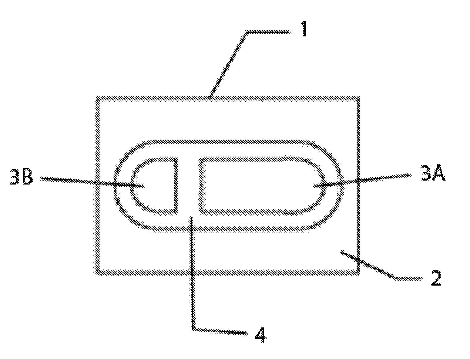
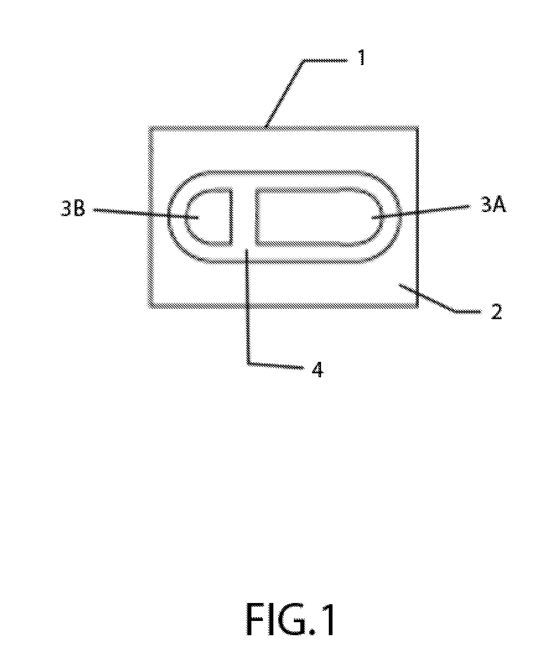
[0024]In the present invention, cover plate (shield) exhibiting ferromagnetic property can be manufactured by compressing then die cut, by complete straight die cut, by injection-mold the cover plate to desirable size and shape, or by sheet metal press technology. Cover plate can be manufactured in shape to control the direction, shape, area, geometry, and concentration of the reflection. The cover plate can be made very small, from as small as 1 mm in area and above. The vacuum coating depositing process will utilize aluminum and silver thin film, or other reflecting materials, to coat the reflection unit in order to achieve maximum reflection rate. The cover plate is placed over the substrate.

[0025]Next a proprietary magnetic holding device, a device such as magnet, is used to hold the cover plate to its place during vacuum coating. Specifically, since the cover plate is made of metal, a material with ferromagnetic property, it is attracted to the magnet where the magnet is placed...


PUM

PropertyMeasurementUnit
Thicknessaaaaaaaaaa
Sizeaaaaaaaaaa
Shapeaaaaaaaaaa

Abstract

The present invention discloses an improved method of LED reflector manufacturing process where the method includes providing a substrate, wherein said substrate comprises a reflector unit, and a Light Emitting Diode; providing a shield member with ferromagnetic property; placing said shield member over the desired area of over the substrate; providing a magnet where said shield member is attracted to; placing said magnet immediately below the substrate wherein said magnet is capable of immobilizing the shield member over the substrate; performing a vacuum deposition coating; and removing the magnet and the shield member.

Description

CROSS REFERENCE TO RELATED APPLICATION[0001]This application claims the benefit of priority under 35 U.S.C. 119(e) to the filing date of U.S. provisional patent application No. 60 / 997,424 entitled “Light Emitting Diode Vacuum Coating by Magnetized Mask” which was filed Oct. 2, 2007, and is incorporated herein by reference.FIELD OF INVENTION[0002]This present invention relates to methods for vacuum coating. Specifically, it is an improved method to perform vacuum coating. More specifically, it is a method of vacuum coating as used to coat the reflection unit as the reflection unit is used in connection with light emitting diode (LED) chip.BACKGROUND OF THE INVENTION[0003]In the past, LED was used as signal(s), instead of being utilized as a lighting source (e.g. flashlights). Recent technological advancements enable LED (Light Emitting Diode) to have better reflection. In general, LED (light emitting device) uses reflection to guide light into a direction. The reflection of light is ...

Claims


Application Information

Patent Timeline
IPC IPC(8): C23C14/34
CPCC23C14/042H01L33/60F21K9/00H01L2224/16245H01L2224/32245H01L2224/48091H01L2224/48247H01L2224/73265F21K9/68H01L2924/00014H01L2924/00
Inventor HSU, ROGER WEN YIHSU, SHU-YUHSU, SHU-HIS
Owner HSU ROGER WEN YI
Why Eureka
Try Eureka