Direct ac power converting apparatus
a technology of power conversion apparatus and direct ac, which is applied in the direction of dc-ac conversion without reversal, motor/generator/converter stopper, dynamo-electric converter control, etc., can solve the problems of complicated circuit construction and increase in cost as a problem
- Summary
- Abstract
- Description
- Claims
- Application Information
AI Technical Summary
Benefits of technology
Problems solved by technology
Method used
Image
Examples
first embodiment
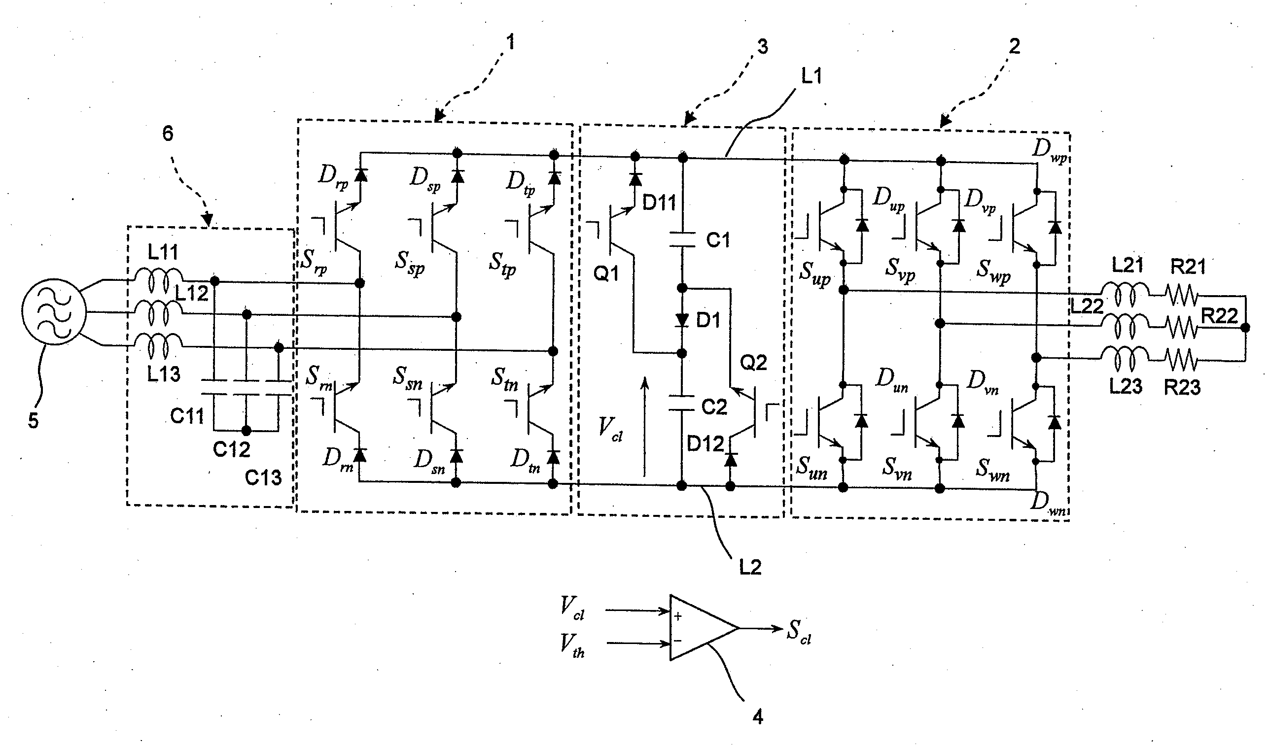
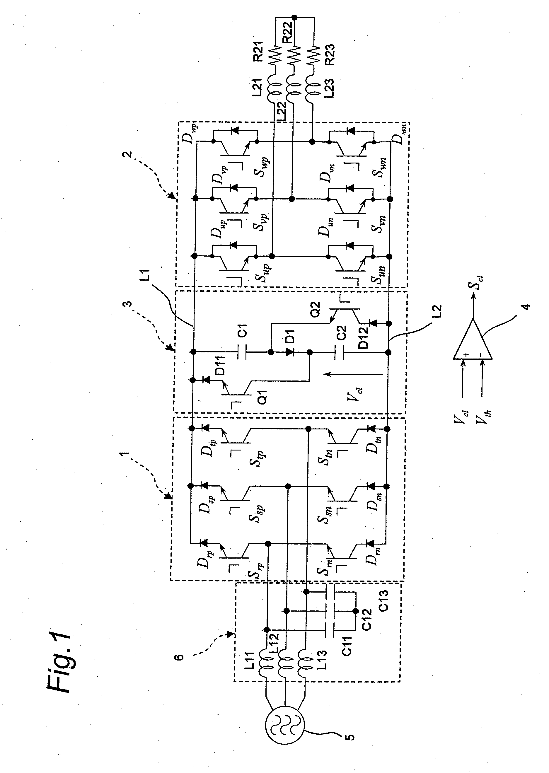
[0060]FIG. 1 shows a constructional view of a direct AC power converting apparatus according to a first embodiment of the invention.
[0061]The direct AC power converting apparatus of this first embodiment, as shown in FIG. 1, includes a converter section 1 composed of transistors Srp, Srn, Ssp, Ssn, Stp, Stn and diodes Drp, Drn, Dsp, Dsn, Dtp, Dtn, an inverter section 2 composed of transistors Sup, Sun, Svp, Svn, Swp, Swn and diodes Dup, Dvp, DVn, Dwn, and a control section (not shown) for outputting control signals to turn on and off the transistors Srp, Srn, Ssp, Ssn, Stp, Stn of the converter section 1 and the transistors Sup, Sun, Svp, Svn, Swp, Swn of the inverter section 2.
[0062]The converter section 1 inputs a phase voltage vr derived from a three-phase AC power supply 5 to a collector of the transistor Srp and an emitter of the transistor Srn via a coil L11. The converter section 1 also inputs a phase voltage vs derived from the three-phase AC power supply 5 to a collector of...
second embodiment
[0072]FIG. 3 shows a constructional view of a direct AC power converting apparatus according to a second embodiment of the invention. The direct AC power converting apparatus of this second embodiment is similar in construction to the direct AC power converting apparatus of the first embodiment except the clamp circuit. Therefore, like constituent members are designated by like reference numerals, and their description is omitted.
[0073]One end of a capacitor C1 as an example of a first capacitance element is connected to the first DC link section L1, and an anode of a diode D1 as an example of a first diode element is connected to the other end of the capacitor C1. One end of a capacitor C2 as an example of a second capacitance element is connected to a cathode of the diode D1, and the other end of the capacitor C2 is connected to the second DC link section L2. Also, an anode of a diode D2 as an example of a second diode element is connected to the cathode of the diode D1, and a cat...
third embodiment
[0097]FIG. 8 is a constructional view of a clamp circuit in a direct AC power converting apparatus according to a third embodiment of the invention. The direct AC power converting apparatus of this third embodiment is similar in construction to the direct AC power converting apparatus of the first embodiment except the clamp circuit. Therefore, like constituent members are designated by like reference numerals, with their description omitted, and FIG. 1 is used also in this case.
[0098]One end of a capacitor C1 as an example of a first capacitance element is connected to the first DC link section L1, and an anode of a diode D1 as an example of a first diode element is connected to the other end of the capacitor C1. One end of a capacitor C2 as an example of a second capacitance element is connected to a cathode of the diode D1, and the other end of the capacitor C2 is connected to an anode of a diode D2 as an example of a second diode element. Further, a cathode of the diode D2 is co...
PUM
 Abstract
Description
Claims
Application Information
 - R&D
- Intellectual Property
- Life Sciences
- Materials
- Tech Scout
- Unparalleled Data Quality
- Higher Quality Content
- 60% Fewer Hallucinations
Browse by: Latest US Patents, China's latest patents, Technical Efficacy Thesaurus, Application Domain, Technology Topic, Popular Technical Reports.
© 2025 PatSnap. All rights reserved.Legal|Privacy policy|Modern Slavery Act Transparency Statement|Sitemap|About US| Contact US: help@patsnap.com


