Directed assembly of triblock copolymers

a triblock and self-assembling technology, applied in the field of nanofabrication techniques, can solve the problems of limited use of directed self-assembly, defects in patterns of approaches relying solely on copolymer self-assembly, and limitations of existing methods of using block copolymer materials

Active Publication Date: 2009-04-02
WISCONSIN ALUMNI RES FOUND
View PDF33 Cites 100 Cited by
  • Summary
  • Abstract
  • Description
  • Claims
  • Application Information

AI Technical Summary

Benefits of technology

[0007]The present invention provides methods of directed self-assembly of multi-block (i.e., triblock and higher-order) copolymers on patterned substrates. According to various embodiments, the methods involve depositing copolymer materials on substrates configured to drive the assembly of micro-phase separated films that exhibit the same morphology as that copolymer materials in the bulk. In certain embodiments, binary patterns are used to drive the triblock copolymer films. The binary two-dimensional surface patterns are transformed into three-component and three-dimensional structures throughout the thickness of the overlying copolymer films. The films formed may be characterized by o

Problems solved by technology

However, existing methods of using block copolymer material suffer from several limitations.
Approaches that rely solely on copolymer self-assembly suffer from defects in t

Method used


Image

  • Directed assembly of triblock copolymers
  • Directed assembly of triblock copolymers
  • Directed assembly of triblock copolymers

Examples


example 1

[0087]A representative example polymerization of poly(isoprene-b-styrene-b-ethylene oxide) (PI—PS—PEO) or PISO for shorthand, is conducted with the following steps. All monomers are purified by destructive distillation while the polymerization solvents are passed over activated silica columns and all reagents are isolated from air and other contaminants. A specified amount of sec-butyllithium is added to cyclohexane followed by isoprene with subsequent polymerization for roughly four hours at 40° C. Addition of styrene along with a small amount of tetrahydrofuran (THF) leads to the rapid crossover from isoprenyllithium to styryllithium and chain growth, again at 40° C. After approximately four hours the reaction is terminated with a ten-fold excess of ethylene oxide followed by addition of HCl in methanol, which terminates each chain with an alcohol group. The PI—PS—OH product is recovered by extraction, precipitation, and washing, then redissolved in THF and reinitiated with potass...

example 2

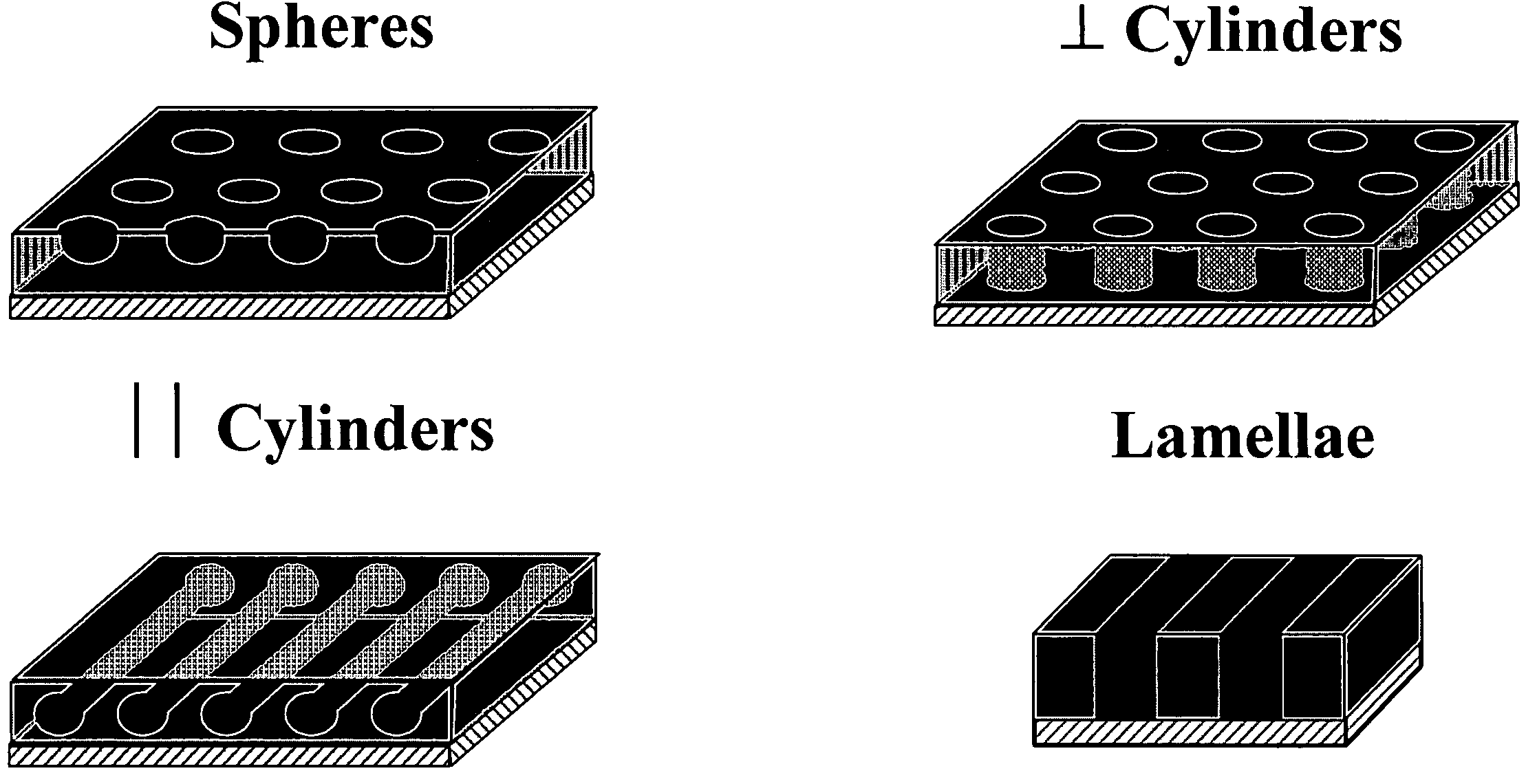
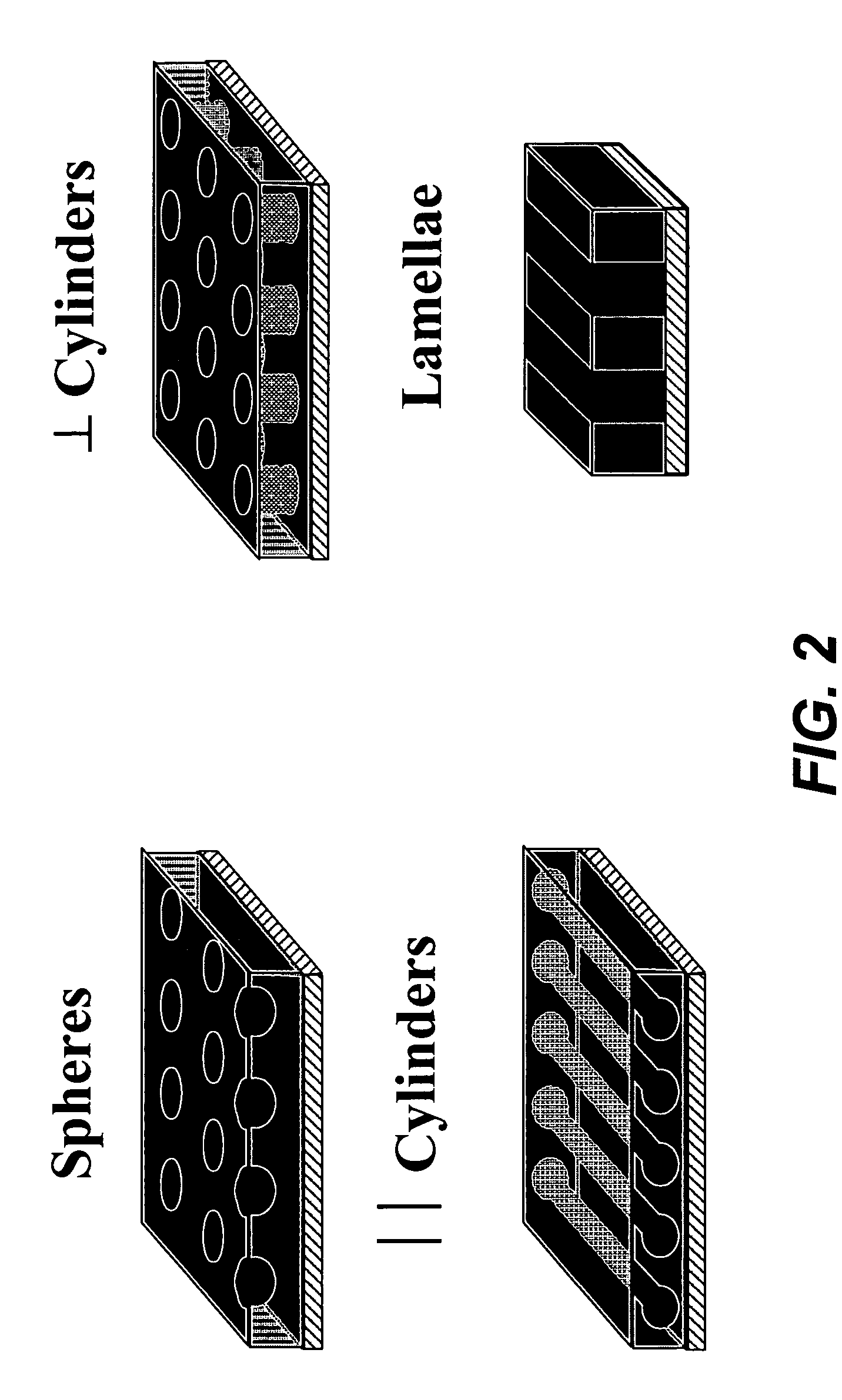
[0088]A triblock copolymer (PEO—PI—PS) that forms three-phase lamellar structures (see structure a in FIG. 3A) was directed to assemble on chemically nanopatterned surfaces having alternating stripes of polar and non-polar functionality. The PEO preferentially wets the polar stripes on the surface, and the PI and PS preferentially wet the non-polar stripes of the surface.

[0089]FIG. 8A shows a schematic representation of the procedure used to create the nanopatterned substrates and FIGS. 8B and 8C show results. First, in FIG. 8A, a representation of the PEO—PI—PS block copolymer is shown, with the PI represented by a dotted pattern, PS a lighter grey solid and PEO a darker grey solid. The binary patterned imaging layer is shown, with the differently striped areas illustrating the patterning. The PEO—PI—PS block copolymer material is then deposited on the binary pattern and direct to self-assemble on the pattern. The result is three-phase lamellar morphology formed by the triblock cop...

example 2a

[0091]A binary striped binary pattern was created on a substrate by depositing a PS brush on the substrate and a photoresist layer on the brush. The photoresist was patterned by EUV interference lithography to create lines 25 nm apart. The photoresist pattern was replicated to the PS brush by exposure to an oxygen plasma. Excess photoresist was then removed using solvent rinses to result in a layer patterned with alternating stripes of a PS brush and an oxygenated PS brush. The pattern period (width of two adjacent stripes) was 50 nm.

[0092]A triblock PISO copolymer (I=33.4%; S=34.2%; 0=32.4% by volume; Phase: Lam3; L0=50.9 nm) was deposited on the binary patterned substrate. The PS brush was wet by PS and PI and the oxygenated PS brush by PEO.

[0093]FIG. 8D shows an image of the assembled PISO. FIG. 8D also shows a schematic of the assembled PISO and its dimensions that is consistent with image and believed to be the resulting structure. As can been seen from the schematic, the PEO a...


PUM

PropertyMeasurementUnit
Dimensionaaaaaaaaaa
Distanceaaaaaaaaaa
Wetting tensionaaaaaaaaaa

Abstract

Methods of directed self-assembly of multi-block (i.e., triblock and higher-order) copolymers on patterned substrates and related compositions are provided. According to various embodiments, the methods involve depositing copolymer materials on substrates configured to drive the assembly of micro-phase separated films that exhibit the same morphology as that copolymer materials in the bulk. In certain embodiments, binary patterns are used to drive the triblock copolymer films. The binary two-dimensional surface patterns are transformed into three-component and three-dimensional structures throughout the thickness of the overlying copolymer films.

Description

CROSS-REFERENCE TO RELATED APPLICATIONS[0001]This application claims priority under 35 USC § 119(e) from U.S. Provisional Application No. 60 / 726,766, filed Oct. 14, 2005, which is hereby incorporated by reference in its entirety and for all purposes.FIELD OF THE INVENTION[0002]The invention relates to methods of nanofabrication techniques. More specifically, the invention relates to patterning materials at the nanoscale level utilizing block copolymers.BACKGROUND OF THE INVENTION[0003]As the development of nanoscale mechanical, electrical, chemical and biological devices and systems increases, new processes and materials are needed to fabricate nanoscale devices and components. This is especially true as the scale of these structures decreases into the tens of nanometers. There is a particular need for materials and methods that are able to duplicate nanoscale patterns over large areas with perfect or near-perfect registration of the pattern features. Block copolymer materials are u...

Claims


Application Information

Patent Timeline
IPC IPC(8): C08G63/48B32B9/04
CPCB81C1/00031G03F7/40B82Y30/00B81C2201/0149Y10T428/31504
Inventor NEALEY, PAUL FRANKLINBATES, FRANK S.PABLO, JUAN J. DE
Owner WISCONSIN ALUMNI RES FOUND
Why Eureka
Try Eureka