Motor vehicle air cooling method and system

a technology for motor vehicles and air cooling, applied in the direction of vessel parts, transportation and packaging, vessel construction, etc., can solve the problems of deterioration of beverage bottles or cans, damage to the stereo system, and the inside temperature of the enclosed space of the car rising soon, so as to save power consumption

Inactive Publication Date: 2009-04-02
LIN CHIEN ERH
View PDF6 Cites 29 Cited by
  • Summary
  • Abstract
  • Description
  • Claims
  • Application Information

AI Technical Summary

Benefits of technology

[0018]According to still another aspect of the present invention, sensor switches are installed in each electric fan and adapted to detect the ambient temperature. When the ambient temperature reaches a predetermined value, each sensor switch switches on the associating electri

Problems solved by technology

However, when a car is parked in an outdoor parking lot and exposed to the radiation of the light of the sun, the temperature of the enclosed inside space of the car rises soon.
Further, when the inside temperature of a car is excessively high, the inflammable articles (disposable cigarette lighter, rosin oil, etc.) carried in a car may explode to damage the stereo system, dashboard or seat coverings.
If beverage bottles or cans are carried in a car, the beverage bottles or cans deteriorate soon when the inside temperature of the car is excessively high.
It is harmful to the health to drink deteriorated beverage.
Further, a high temperature may cause the plastic or chemical materials of the car to release volatized organic substances (such as toluene, ethylbenzene, decyl aldehyde, dodecane) and formaldenyde.
Breathing in a certain concentration of these substances will cause damage to the human body.
Further, exposing a car to a high temperature environment for long will shorten the service life of the internal devices or parts of the car.
Further, when the temperature inside a car is much higher than the temperature outside the car, it gives a burden to the air conditioner of the car, and it takes much time to lower the inside temperature of the car.
Operating the air conditioner of a car under this condition will increase fuel consumption of the car and shorten the service life of the air conditioner.
However, the car may be stolen easily or

Method used


Image

  • Motor vehicle air cooling method and system
  • Motor vehicle air cooling method and system
  • Motor vehicle air cooling method and system

Examples


Embodiment Construction

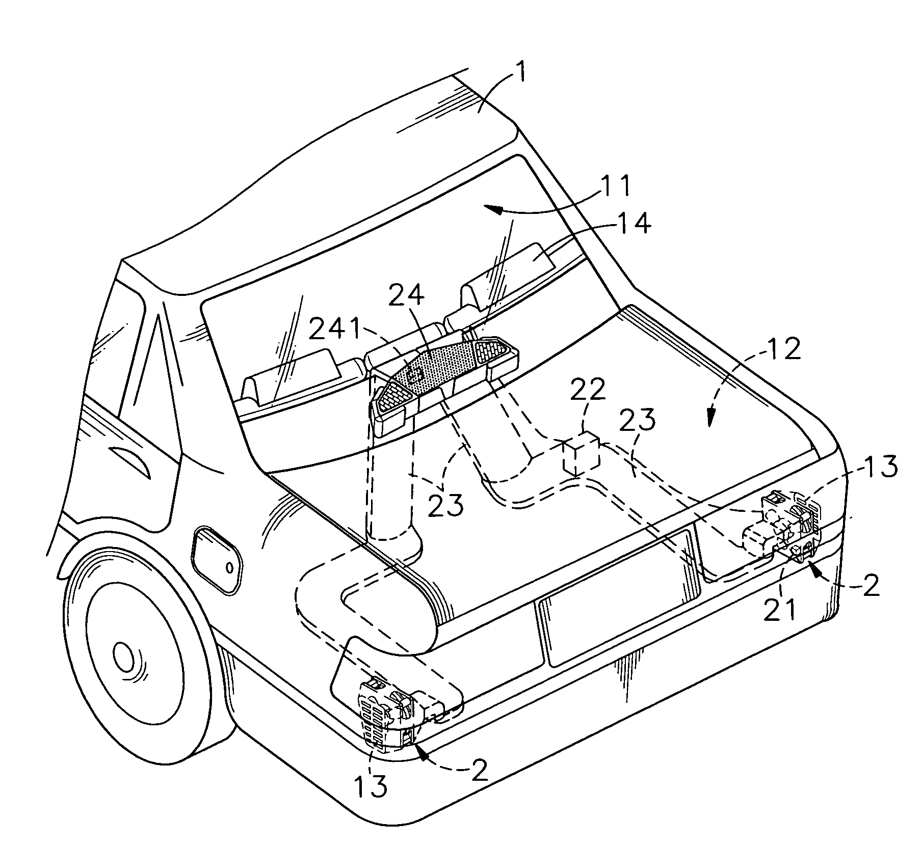
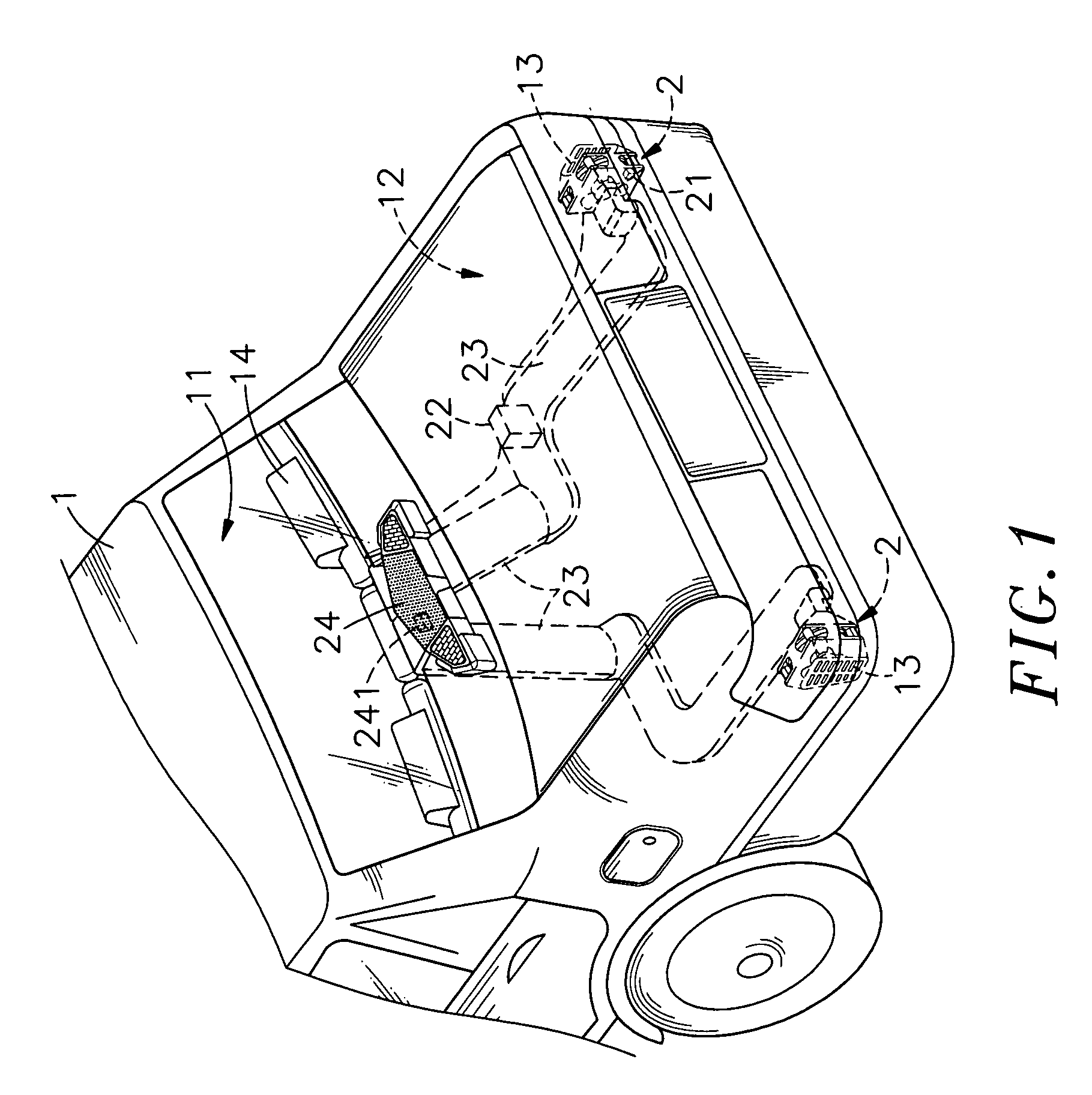
[0029]Referring to FIGS. 1 and 2, a motor vehicle air cooling method in accordance with the present invention is installed to a motor vehicle cooling system 2 in a motor vehicle 1.

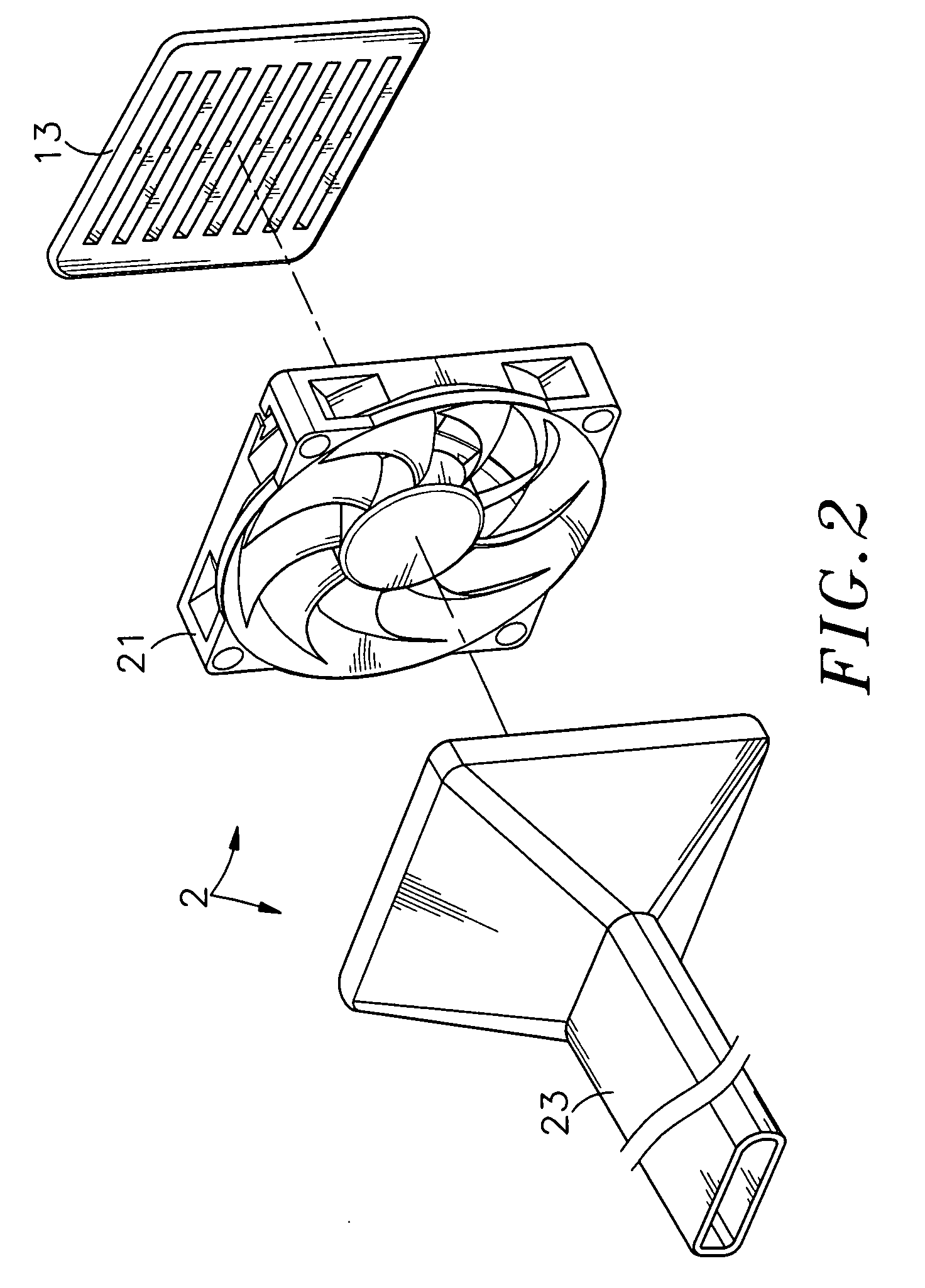
[0030]At least one, for example, two ventilation panels 13 are mounted inside a trunk 12 of the motor vehicle 1 near the rear bumper. When the internal air pressure of the motor vehicle 1 surpasses the atmosphere, the internal air pressure forces the plastics (or rubber) louvers of the ventilation panels 13 to bias from the close position to the open position, and therefore the internal air pressure is released. The motor vehicle cooling system 2 according to the present preferred embodiment comprises two first electric fans 21 respectively installed in the ventilation panels 13. Each first electric fan 21 has a suction side facing the inside of the trunk 12, and an exhaust side facing the associating ventilation panel 13. Therefore, the first electric fans 21 suck air from the trunk 12, and exhaust air to...


PUM


Abstract

A motor vehicle air cooling method and system in which electric fans are installed in the rear side of a motor vehicle to draw hot air out of the inside space of the motor vehicle so as to cause negative pressure in the motor vehicle for sucking outside cooling air into the inside of the motor vehicle to have the pressure inside the motor vehicle be in balance with the pressure outside the motor vehicle and to simultaneously lower the temperature in the motor vehicle after an air conditioner ventilation panel of the motor vehicle has been set in an outer loop status.

Description

BACKGROUND OF THE INVENTION[0001]1. Field of the Invention[0002]The present invention relates to a motor vehicle air cooling measures and more particularly, to a motor vehicle air cooling method and system in which electric fans are installed in the rear side of the motor vehicle to draw air out of the motor vehicle and to cause negative pressure in the motor vehicle for sucking outside cooling air into the inside of the motor vehicle to have the pressure inside the motor vehicle be in balance with the pressure outside the motor vehicle and to simultaneously lower the temperature in the motor vehicle after the air conditioner ventilation panel of the motor vehicle has been set in an outer loop status.[0003]2. Description of the Related Art[0004]Following change in living conditions and popularization of cars, many people use a car as one's personal transportation vehicle. However, when a car is parked in an outdoor parking lot and exposed to the radiation of the light of the sun, th...

Claims


Application Information

Patent Timeline
IPC IPC(8): B60H1/00
CPCB60H1/248B60H1/244
Inventor LIN, CHIEN-ERH
Owner LIN CHIEN ERH
Why Eureka
Try Eureka