Wear leveling method and controller using the same

Active Publication Date: 2009-04-02
PHISON ELECTRONICS
View PDF1 Cites 174 Cited by
  • Summary
  • Abstract
  • Description
  • Claims
  • Application Information

AI Technical Summary

Benefits of technology

[0018]The present invention provides a wear leveling method, wherein blocks in a non-volatile memory are used eve

Problems solved by technology

However, blocks in a flash memory can be erased only a limited number of times, for example, a block in a flash memory is worn-out after being erased 10,000 times. Data loss may be caused when the storage capacity or performance of a flash memory is obviously deteriorated by its worn-out blocks.
Generally speaking, the existence of worn-out blocks will reduce the performance of a flash memory even if the wear of other blocks are still relatively low.
Besides the deterioration in the performance of the worn-out blocks, the performance of the entire flash memory is also re

Method used


Image

  • Wear leveling method and controller using the same
  • Wear leveling method and controller using the same
  • Wear leveling method and controller using the same

Examples


first embodiment

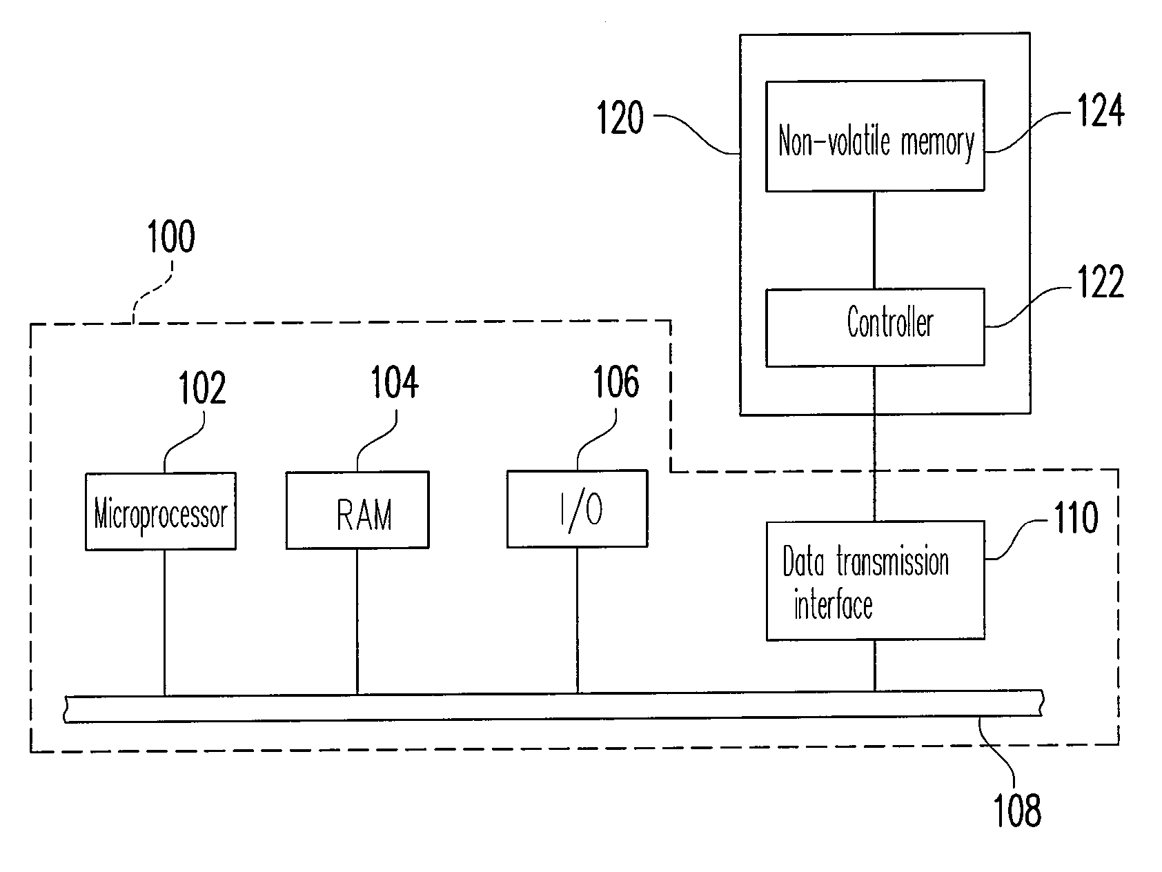
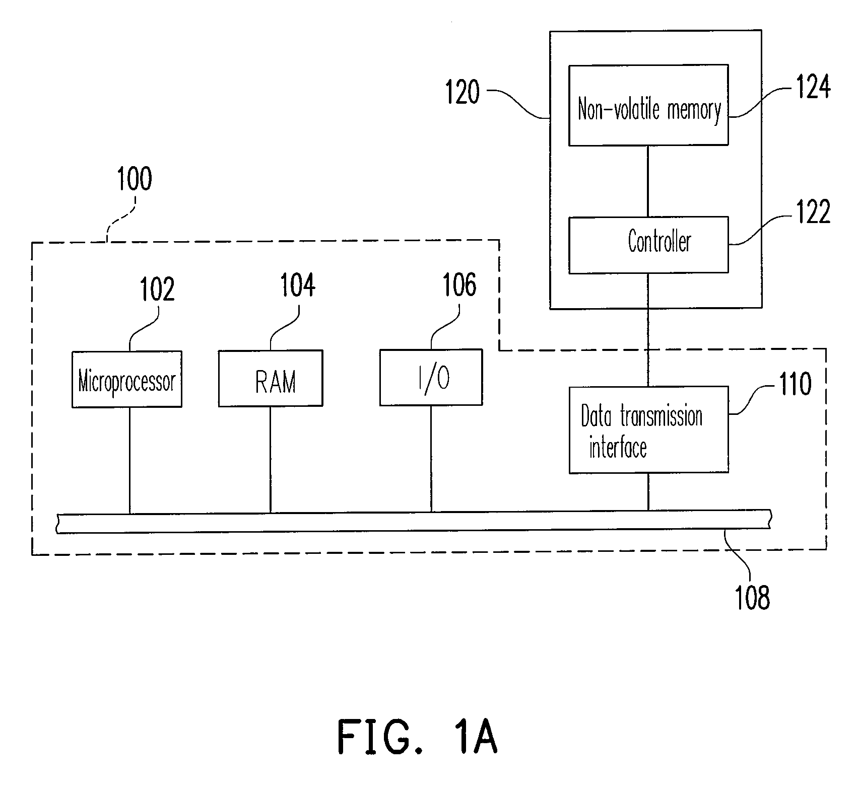
[0035]FIG. 1A illustrates a host having a non-volatile memory storage device according to the first embodiment of the present invention.

[0036]Referring to FIG. 1A, the host 100 includes a microprocessor 102, a random access memory (RAM) 104, an input / output (I / O) device 106, a system bus 108, and a data transmission interface 110. It should be noted that the host 100 may further include other components, such as a display or a network device.

[0037]The host 100 may be a computer, a digital camera, a video camera, a communication device, an audio player, or a video player. Generally speaking, the host 100 can be any system which can store data.

[0038]In the present embodiment, the non-volatile memory storage device 120 is electrically connected to other components of the host 100 through the data transmission interface 110. Data can be written into or read from the non-volatile memory storage device 120 through the microprocessor 102, the RAM 104, and the I / O device 106. The non-volati...

second embodiment

[0088]The hardware structure, the operation of the non-volatile memory, and the recording of the block erase counts in the second embodiment of the present invention are the same as those in the first embodiment (as shown in FIGS. 1A˜1B, 2A˜2B, and 4A˜4D) therefore will not be described herein. The difference between the second embodiment and the first embodiment is that in the second embodiment, a selection condition is specified to blocks which are to be used only in the substitute area.

[0089]FIG. 5 is a flowchart of a wear leveling method according to the second embodiment of the present invention. Referring to FIG. 5, the difference of the flowchart illustrated in FIG. 5 from the flowchart illustrated in FIG. 3 is that in step S1310′, a selection condition is specified only to blocks which are to be used in the substitute area 208. In the second embodiment, the selection condition for selecting blocks to be used in the substitute area 208 and the other steps of the wear leveling...

third embodiment

[0090]The hardware structure, the operation of the non-volatile memory, and the recording of the block erase counts in the third embodiment of the present invention are the same as those in the first embodiment (as shown in FIGS. 1A˜1B, 2A˜2B, and 4A˜4D) therefore will not be described herein. The difference between the third embodiment and the first embodiment is that in the third embodiment, a selection condition is specified to blocks which are to be used only in the temporary area.

[0091]FIG. 6 is a flowchart of a wear leveling method according to the third embodiment of the present invention. Referring to FIG. 6, the difference of the flowchart illustrated in FIG. 6 from the flowchart illustrated in FIG. 3 is that in step S1310″, a selection condition is specified to only blocks which are to be used in the temporary area 210. In the third embodiment, the selection condition for selecting blocks to be used in the temporary area 210 and the other steps of the wear leveling method ...


PUM


Abstract

A wear leveling method for a non-volatile memory is provided. The non-volatile memory is substantially divided into a plurality of blocks, and these blocks are grouped into at least a data area, a spare area, a substitute area, and a temporary area. The wear leveling method includes selecting blocks from the spare area according to different purposes and executing a wear leveling procedure.

Description

CROSS-REFERENCE TO RELATED APPLICATION[0001]This application claims the priority benefit of Taiwan application serial no. 96135924, filed on Sep. 27, 2007. The entirety of the above-mentioned patent application is hereby incorporated by reference herein and made a part of this specification.BACKGROUND OF THE INVENTION[0002]1. Field of the Invention[0003]The present invention generally relates to a wear leveling method, in particular, to a wear leveling method for a non-volatile memory and a controller using the same.[0004]2. Description of Related Art[0005]Along with the widespread of digital cameras, camera phones, and MP3 in recently years, the consumers' demand to storage media has increased drastically too. Flash memory is one of the most adaptable memories for such battery-powered portable products due to its characteristics such as data non-volatility, low power consumption, small volume, and non-mechanical structure. Besides being applied in foregoing portable products, flash...

Claims


Application Information

Patent Timeline
IPC IPC(8): G06F12/00
CPCG06F2212/7211G06F12/0246
Inventor YEH, CHIH-KANG
Owner PHISON ELECTRONICS
Why Eureka
Try Eureka