Capacitive touch switch and domestic appliance provided with such switch

a touch switch and capacitive technology, applied in the field of capacitive touch switches, can solve the problems of increasing the overall cost increasing the physical dimension, and reducing the overall thickness of the control panel, so as to increase the overall thickness of the glass ceramic cooking hob and limit the thickness

Inactive Publication Date: 2009-04-09
WHIRLPOOL CORP
View PDF11 Cites 66 Cited by
  • Summary
  • Abstract
  • Description
  • Claims
  • Application Information

AI Technical Summary

Benefits of technology

[0015]The capacitive touch switch according to the present invention is adapted to be used in association with a glass ceramic surface used in cooking appliances. Due to its limited thickness, the touch switch according to the invention does not increase the overall thickness of glass ceramic cooking hobs. Moreover, it is adapted to be used on glass doo

Problems solved by technology

The use of opaque walls increases physical dimensions and renders the mounting quite complex.
Electrodes can also be made of transparent conductive material (such as indium tin oxide), located between the light guide and the lower surface of the transparent cover under which the touch switch is placed, with an increase of the overall cost of the control pan

Method used


Image

  • Capacitive touch switch and domestic appliance provided with such switch
  • Capacitive touch switch and domestic appliance provided with such switch
  • Capacitive touch switch and domestic appliance provided with such switch

Examples


second embodiment

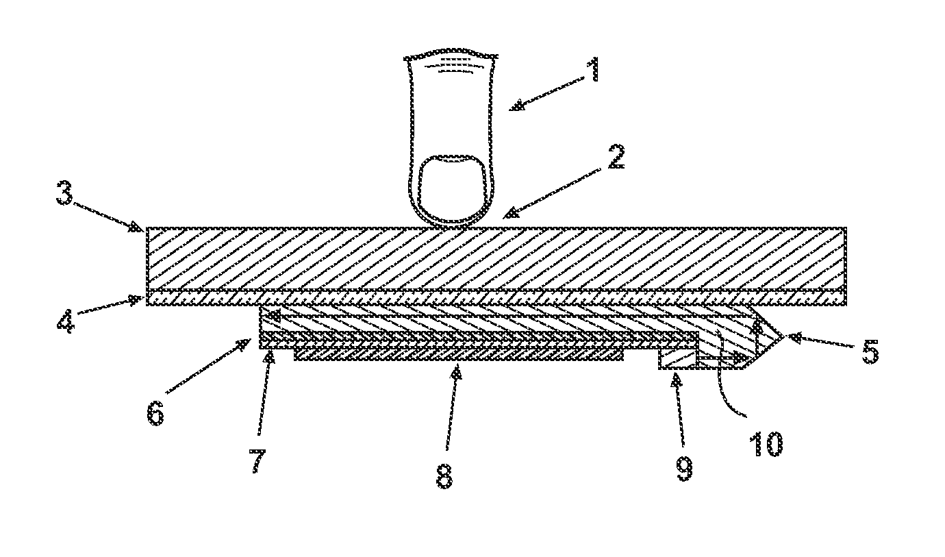
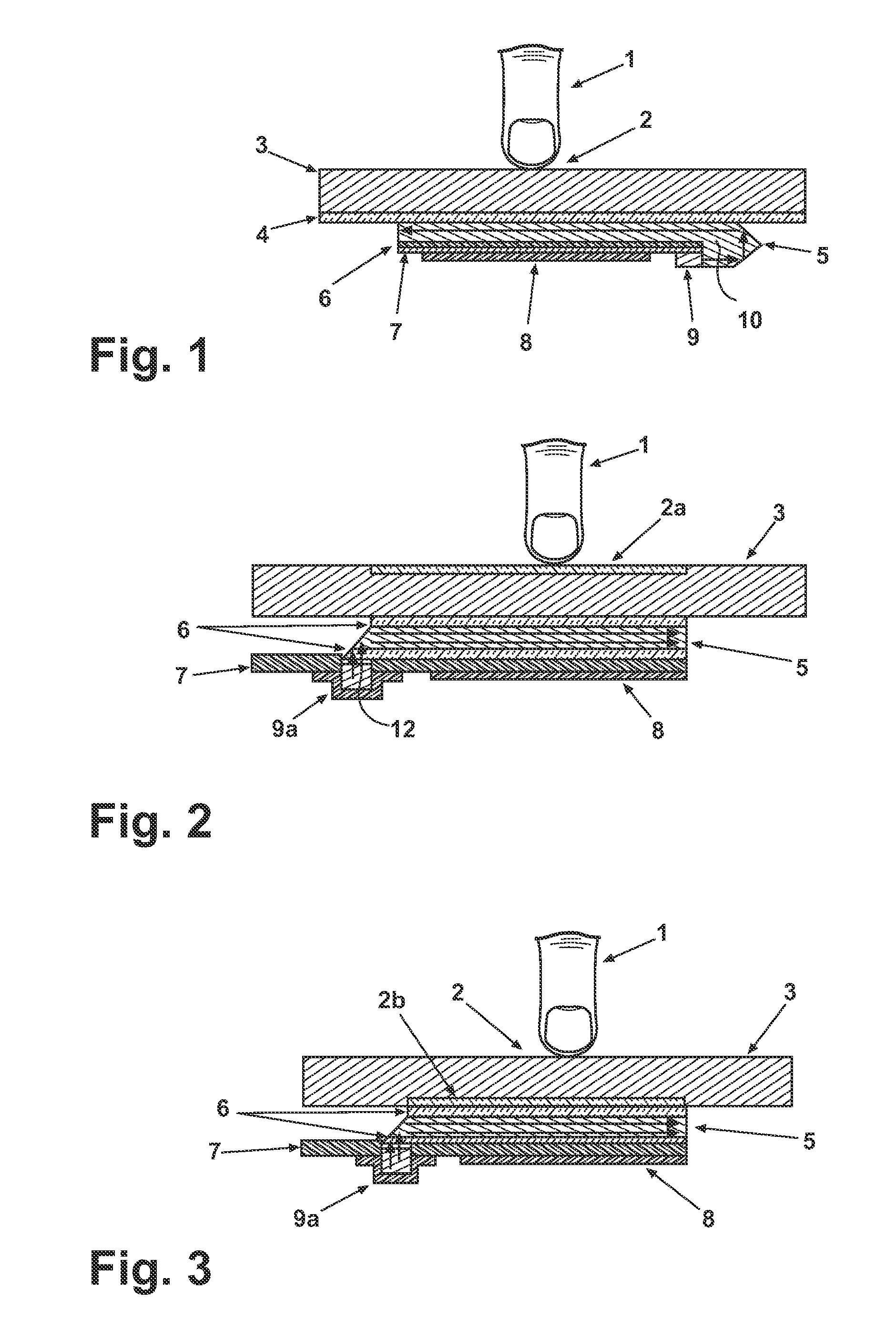
[0030]FIG. 2, in which similar components have been indicated with the same reference numerals of FIG. 1, relates to the invention in which an icon serigraphy 2a is placed on the touch sensitive area. A reverse mounted light emitting diode (LED) 9a is placed on an opening or cutout 12 provided in the single side PCB 7, so that light can enter the light guide 5 from the bottom (with reference to an horizontal mounting of the touch switch). When the LED 9a is switched on, the user can detect the shape of the icon 2a (which for instance can indicate a specific function of the appliance).

third embodiment

[0031]A third embodiment is shown in FIG. 3, which differs from the previous embodiment by a different placing of the icon serigraphy 2a that, in this case, is sandwiched between the transparent ceramic glass or plastic cover 3 and the light guide 5 (with the interposition of the adhesive layer 6). Also in this embodiment, as in the one of FIG. 1, a dark effect on the external transparent touch sensitive area is obtained when the switch is off (i.e. not illuminated).

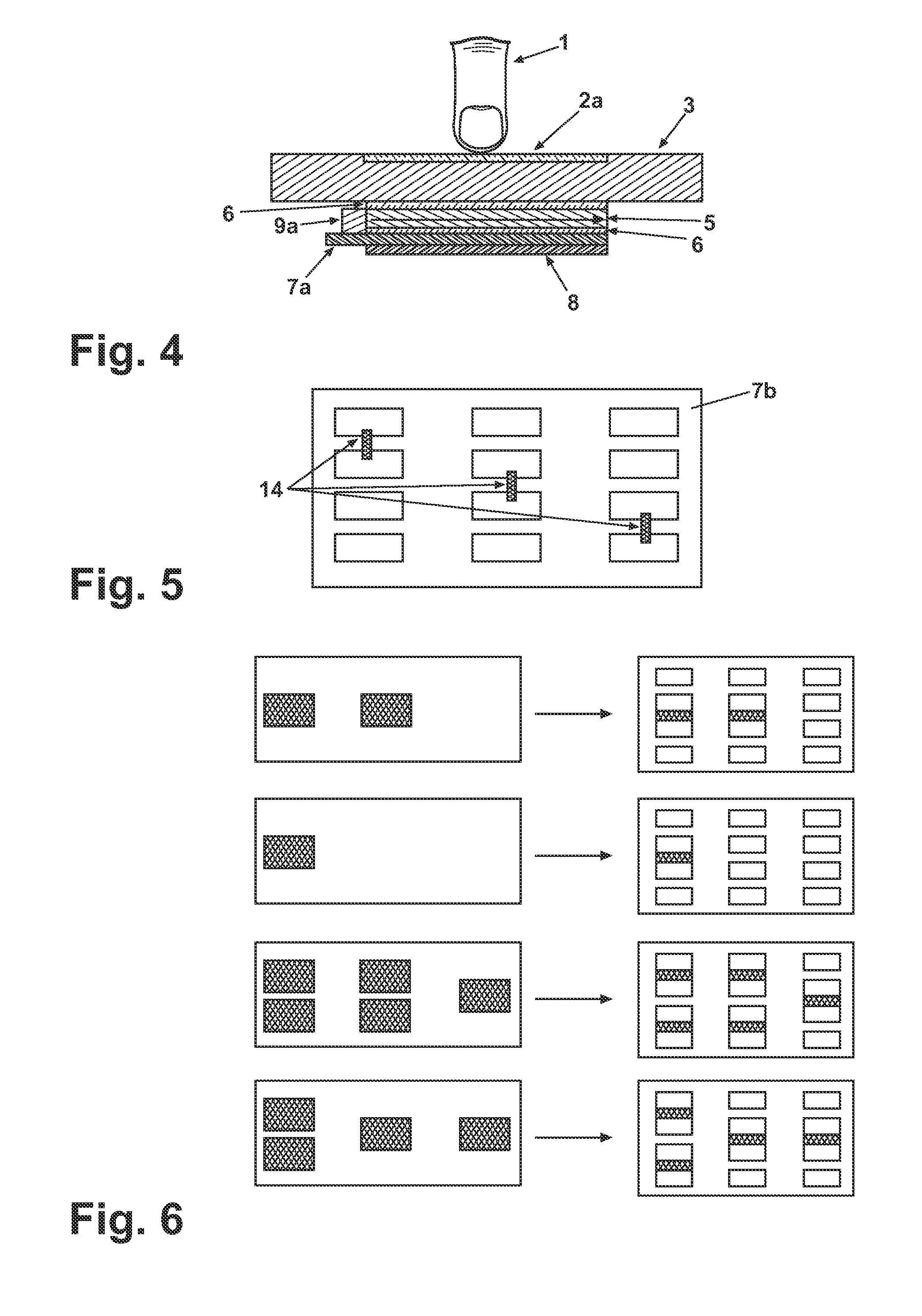
[0032]In the embodiment of FIG. 4 the light emitting diode 9b is fixed to a side of a double side PCB 7a facing the light guide 5. In this embodiment the light from LED 9b is entering an edge of the light guide 5.

[0033]FIG. 5 relates to a plurality of capacitive touch switches associated to a general printed circuit board 7b where the small pads or electrodes can be connected with soldered bridges or jumpers 14 in order to create a bigger pad from smaller pads. According to traditional technology, several available capac...


PUM


Abstract

A capacitive touch switch having a printed circuit board and capacitive electrode provided on a surface of the printed circuit board is disclosed. The printed circuit board is interposed between a transparent planar light guide and the electrode, the planar light guide being attached to a first face of a transparent cover whose second face is adapted to be touched by the user, a light source being connected to the printed circuit board and being able to convey light to the planar light guide.

Description

BACKGROUND OF THE INVENTION[0001]1. Field of the Invention[0002]The present invention relates to a capacitive touch switch to be used on control panels of domestic appliance such as cooking ovens, cooking hobs, microwave ovens or the like. The invention particularly refers to a capacitive touch switch comprising a control board and capacitive detecting means provided on a surface of the control board.[0003]2. Description of the Related Art[0004]With the term “switch” we mean every kind of touch sensors which usually replace the traditional buttons in modern flush user interfaces.[0005]Visual feedback activation of a touch switch control is simply provided by a light source, for example a light emitted diode (LED). Usually several touch switches are arranged, together with control board thereof, in a control panel.[0006]To avoid optical interference between adjacent touch switches, light flux shall be conveyed from a light source to the related touch sensitive switch surfaces.[0007]O...

Claims


Application Information

Patent Timeline
IPC IPC(8): H03K17/975
CPCH03K17/962H03K2217/96079H03K2217/96077
Inventor ZEIJLON, ANDERS BJORNGORANSSON, BJORNARENA, GIUSEPPELAZZAROTTO, ROBERTOARIONE, ETTORE
Owner WHIRLPOOL CORP
Why Eureka
Try Eureka