
Display apparatus and method of producing the same

Inactive Publication Date: 2009-04-09
CANON KK
View PDF4 Cites 9 Cited by
  • Summary
  • Abstract
  • Description
  • Claims
  • Application Information

AI Technical Summary

Benefits of technology

[0020]The present invention has been proposed in view of the above-described situation and provides a display apparatus having auxiliary electrodes for which a high definition and a high yield can be realized.
[0026]According to the display apparatus of the present invention, since the film thickness of each the first auxiliary electrodes is small, the position of an alignment mark for a shadow mask disposed on an organic EL substrate can be confirmed even after the first auxiliary electrodes are formed using the shadow mask. Accordingly, by shifting the shadow mask in a direction parallel to the resulting auxiliary wiring after the completion of the alignment step using an alignment mark, another auxiliary wiring can be formed using the same shadow mask. As a result, continuous auxiliary wiring can be formed while ensuring the strength of the shadow mask and any increase in the process time due to a performance of a vapor deposition process a plurality of times, can be minimized.

Problems solved by technology

In such a case, the resistance of the second electrode increases, and thus voltage drop tends to readily occur.
Consequently, the voltage may become nonuniform due to the in-plane resistance of the second electrode on the light extraction side, thereby degrading the display quality due to a decrease in the response speed, an increase in the electric power consumption, or the like.
Accordingly, the structure of the apparatus may become complex.
As a result, it becomes difficult to arrange the auxiliary electrode in a non-light-emitting area.
Accordingly, the process of forming the auxiliary electrodes is complex.

Method used


Image

  • Display apparatus and method of producing the same
  • Display apparatus and method of producing the same
  • Display apparatus and method of producing the same

Examples


example

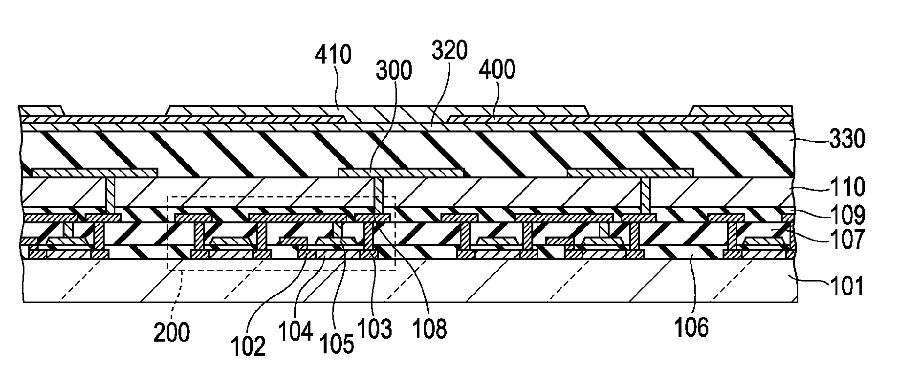
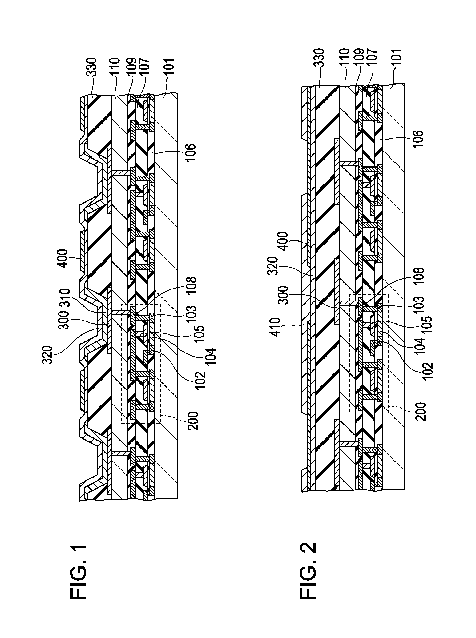
[0072]Next, an example of a method of producing the display apparatus having the above-described structure and a specific example of a top-emission-type organic EL display apparatus, which has a more specific structure than the above display apparatus, will be described in the order of a production procedure with reference to FIGS. 5A to 7B. FIGS. 5A to 7B are cross-sectional views showing steps of a process of producing an organic EL element in the display apparatus according to an Example of the present invention.

[0073]First, as shown in FIG. 5A, a TFT 200 and source and drain electrodes thereof were formed on a substrate 101 composed of, for example, a glass substrate. Subsequently, in order to planarize irregularities formed on a surface of the substrate 101 by the formation of the TFT 200 and the electrodes, a planarizing film 110 was formed on the substrate 101. In this case, for example, a positive photosensitive polyimide is applied on the substrate 101 by spin coating. Patt...


PUM


Abstract

A display apparatus includes a display substrate having an element isolation film surrounding peripheral edges of a plurality of first electrodes, and a laminated area composed of a second electrode and auxiliary electrodes and disposed on the element isolation film. Each of the auxiliary electrode is composed of first auxiliary electrodes arranged in a broken line pattern, and second auxiliary electrodes provided on the first auxiliary electrodes so as to cover areas where the first auxiliary electrodes are not provided. A wiring interval between auxiliary electrodes is smaller than a wiring length of an auxiliary electrode, and the film thickness of each of the first auxiliary electrodes is in the range of 5 to 30 nm.

Description

BACKGROUND OF THE INVENTION[0001]1. Field of the Invention[0002]The present invention relates to a display apparatus including light-emitting elements and a method of producing the same.[0003]2. Description of the Related Art[0004]An organic electroluminescent element utilizing electroluminescence (hereinafter referred to as “EL”) of an organic material includes a first electrode and a second electrode disposed so as to face each other, and an organic layer disposed between the electrodes. Such an organic EL element has attracted attention as a light-emitting element that can realize high-luminance light emission by low-voltage driving.[0005]An active matrix display apparatus (organic EL display) utilizing such an organic EL element includes thin-film transistors (hereinafter referred to as “TFTs”) corresponding to respective pixels on a substrate. Organic EL elements are arranged on an interlayer insulating film provided so as to cover the TFTs. Each of the organic EL elements incl...

Claims


Application Information

Patent Timeline
IPC IPC(8): H01J9/00H01J1/62
CPCH05B33/26H01L51/5221H10K59/80522H10K59/173H10K2102/351H10K50/824
Inventor YOSHINAGA, HIDEKI
Owner CANON KK
Features
  • Generate Ideas
  • Intellectual Property
  • Life Sciences
  • Materials
  • Tech Scout
  • Unparalleled Data Quality
  • Higher Quality Content
  • 60% Fewer Hallucinations
Learn More