Image Display Apparatus, Electronic Device, Portable Terminal Device, and Method of Displaying Image

a technology of image display and electronic equipment, applied in image memory management, instruments, computing, etc., can solve the problems of lowering the transmittance and reflectivity of one pixel, failure to achieve image displaying with high efficiency, and limited resolution and grayscales, so as to achieve higher efficiency and image quality. the effect of high quality

Active Publication Date: 2009-04-09
JAPAN DISPLAY WEST
View PDF15 Cites 32 Cited by
  • Summary
  • Abstract
  • Description
  • Claims
  • Application Information

AI Technical Summary

Benefits of technology

[0020]The present invention is made in consideration of the above-described respects, and is to provide, for a multi-bit memory system, an image display, electronic apparatus, portable apparatus, and an image displaying method that can solve all of these drawbacks and allow image displaying with higher efficiency and higher image quality compared with conventional techniques.
[0022]According to the configuration of the present invention, in application to an image display device including a display unit that has pixels arranged in a matrix, a vertical driver that outputs a gate signal to the display unit, a horizontal driver that distributes and outputs input image data to signal lines of the display unit, and a timing generator that outputs a timing signal for reference of operation to the display unit, the horizontal driver, and the vertical driver, the input image data is multi-bit image data, and the pixel includes a memory part that is supplied with and holds the input image data output to the signal line selectively in accordance with the gate signal, and represents a grayscale based on time-division driving in accordance with the input image data held in the memory part. Due to this configuration, for image displaying based on a multi-bit memory system, the pixel can be fabricated with an electrode having an area larger than that of an electrode used in the area-ratio grayscale method. This can reduce a useless region among the electrodes and can prevent the occurrence of a fixed pattern. Furthermore, the limitation on the resolution and the number of grayscales due to the processing accuracy of the electrode is alleviated, and the number of semiconductor elements can be reduced. Due to these advantages, by a multi-bit memory system, image displaying can be performed with higher efficiency and higher image quality compared with conventional techniques.
[0024]According to the configuration of the present invention, by a multi-bit memory system, image displaying can be performed with higher efficiency and higher image quality compared with conventional techniques.
[0026]According to the configuration of the present invention, by a multi-bit memory system, image displaying can be performed with higher efficiency and higher image quality compared with conventional techniques.
[0028]According to the configuration of the present invention, by a multi-bit memory system, image displaying can be performed with higher efficiency and higher image quality compared with conventional techniques.
[0029]The present invention can provide, for image displaying based on a multi-bit memory system, electronic apparatus, portable apparatus, and an image displaying method that can solve all of drawbacks in conventional techniques and allow image displaying with higher efficiency and higher image quality compared with conventional techniques.

Problems solved by technology

This yields the useless region that does not contribute to displaying in one pixel, which results in a drawback of the lowering of the transmittance and reflectivity of one pixel.
This causes a problem of failure in image displaying with high efficiency.
This yields a drawback that a fixed pattern dependent upon the arrangement of the sub-pixels is visually recognized at specific grayscales.
In addition, there is a drawback that the resolution and the number of grayscales are limited by the processing accuracy of the sub-pixel having the smallest area.
Moreover, there is also a drawback that a large number of semiconductor elements need to be provided in one pixel and thus the resolution and the number of grayscales are limited.
For these reasons, the above-described system involves a problem that the image quality is insufficient in practical use.

Method used


Image

  • Image Display Apparatus, Electronic Device, Portable Terminal Device, and Method of Displaying Image
  • Image Display Apparatus, Electronic Device, Portable Terminal Device, and Method of Displaying Image
  • Image Display Apparatus, Electronic Device, Portable Terminal Device, and Method of Displaying Image

Examples


first embodiment

(2) Operation of First Embodiment

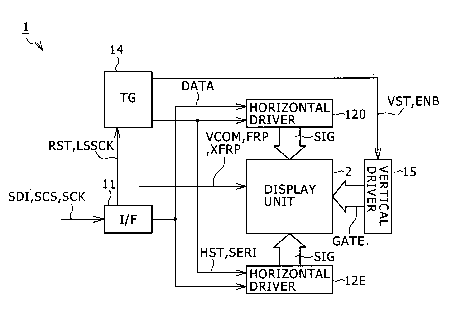
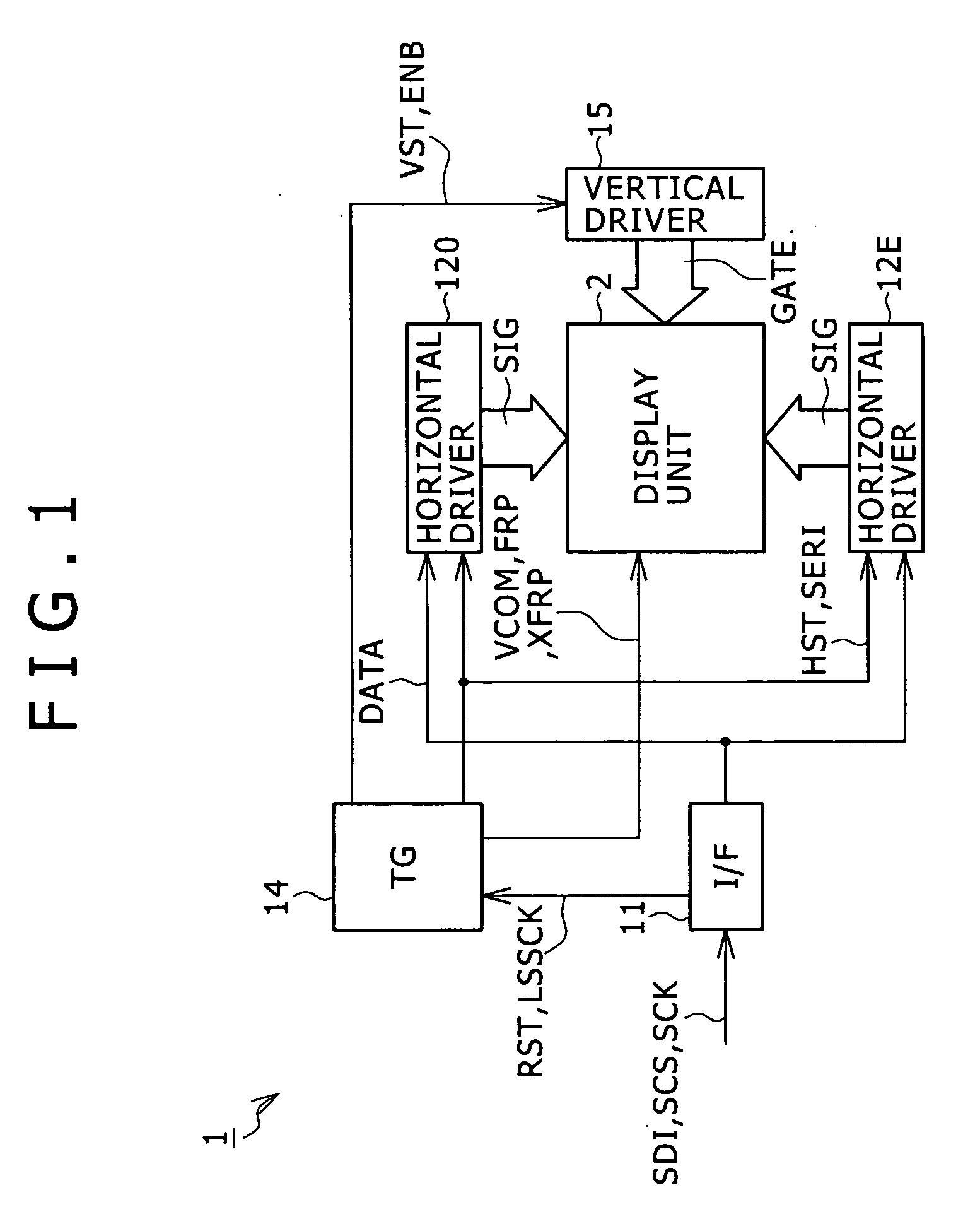
[0082]Based on the above-described configuration, in this image display device 51 (FIG. 9), image data SDI as serial data input via the interface 11 is separated for the odd-numbered lines and the even-numbered lines so as to be input to the horizontal drivers 12O and 12E, and is distributed therein toward the respective signal lines SIG of the display unit 52 (FIG. 5), followed by being converted into one-bit serial data and output to the respective signal lines SIG of the display unit 52 (FIG. 6). Furthermore, in linkage with the driving of the signal lines SIG by the horizontal drivers 12O and 12E, the gate signal GATE is produced by the vertical driver 15 and supplied to the display unit 52, so that the image data output from the horizontal drivers 12O and 12E to the signal lines SIG is sequentially input to the corresponding pixel so as to be used for displaying. This allows the image display device 51 to display an image based on the image data...

second embodiment

(4) Second Embodiment

[0094]FIG. 15 is a connection diagram for showing, based on comparison with FIG. 10, one pixel in a display unit applied to an image display device according to a second embodiment of the present invention. In the image display device according to this embodiment, an electrode 83 relating to this pixel 82A is formed by the combination of a transparent electrode and a reflective electrode. The image display device according to this embodiment is formed to have the same configuration as that of the image display device 51 of the first embodiment, except that this pixel configuration is different.

[0095]According to this embodiment, also when the electrode of the liquid crystal cell is formed by the combination of a transparent electrode and a reflective electrode, the same advantageous effects as those by the first embodiment can be achieved.

third embodiment

(5) Third Embodiment

[0096]FIG. 16 is a connection diagram for showing, based on comparison with FIG. 10, one pixel in a display unit applied to an image display device according to a third embodiment of the present invention. In this third embodiment, the grayscale is represented based on the combination with the area-ratio grayscale method. Therefore, in this embodiment, the electrode of the liquid crystal cell is composed of plural sub-electrodes. Furthermore, for the respective bits of input image data, the values arising from multiplication of the area of the sub-electrode used for displaying by the length of the drive period are so designed as to have a relationship of the ratio of powers of two each corresponding to a respective one of the bit positions.

[0097]Specifically, a pixel 92A is formed to include three sub-electrodes 93A, 93B, and 93C: this number of sub-electrodes is smaller than the number of bits of image data. The areas of these three sub-electrodes 93A, 93B, and ...


PUM


Abstract

The present invention is applied to e.g. a liquid crystal display apparatus based on a multi-bit memory system. In the invention, input image data (SIG) is recorded in a memory part 62 in each pixel, and the grayscale is represented by time-division driving in accordance with the input image data (SIG) recorded in this memory part 62.

Description

BACKGROUND OF THE INVENTION[0001]1. Technical Field[0002]The present invention relates to an image display device, electronic apparatus, portable apparatus, and an image displaying method, and can be applied to e.g. a liquid crystal display based on a multi-bit memory system. According to the present invention, input image data is recorded in a memory part of each pixel, and the grayscale is represented by time-division driving in accordance with the input image data recorded in the memory part. By this feature, in image displaying by a multi-bit memory system, images are displayed with higher efficiency and higher image quality compared with conventional techniques.[0003]2. Background Art[0004]Conventionally, for a liquid crystal display, there has been proposed a so-called area-ratio grayscale system in Japanese Patent Laid-Open No. 2005-1641814 and so on. In this system, one pixel is composed of plural sub-pixels having different areas, and the grayscale of each pixel is varied b...

Claims


Application Information

Patent Timeline
Patent Type & Authority Applications(United States)
IPC IPC(8): G06T1/60
CPCG09G3/2022G09G3/2074G09G3/3659G09G3/3677G09G3/3688G09G2340/0428G09G2300/0809G09G2300/0814G09G2300/0857G09G2310/027G09G2310/0297G09G2300/0456G02F1/133G09G3/20G09G3/36G09G5/39
Inventor TERANISHI, YASUYUKINAKAJIMA, YOSHIHARUKIDA, YOSHITOSHINAKANISHI, TAKAYUKI
Owner JAPAN DISPLAY WEST
Why Eureka
Try Eureka