Vehicle Creep Control in a Hybrid Electric Vehicle

a hybrid electric vehicle and electric vehicle technology, applied in electric propulsion mounting, vehicle rollback, transportation and packaging, etc., can solve the problems of increasing the clutch torque capacity, affecting the control of engine idle speed, and reducing creep speed, so as to enhance the control of powershift transmission and improve creep performan

Active Publication Date: 2009-04-09
FORD GLOBAL TECH LLC
View PDF11 Cites 43 Cited by
  • Summary
  • Abstract
  • Description
  • Claims
  • Application Information

AI Technical Summary

Benefits of technology

[0012]An advantage of the vehicle creep control system is its use of the additional propulsion paths and power sources to improve vehicle creep performance and account for the problems and deficiencies found in a conventional vehicle with a powershift transmission. The control strategy supports multiple HEV powertrain operating modes during vehicle creep conditions by blending torque produced by multiple power sources which are transmitted through multiple propulsion paths during vehicle creep conditions.
[0013]The vehicle creep control enhances powershift transmission control by providing coordinated clutch torque capacity control when vehicle creep is provided or assisted by the additional electric machines. The control is robust and provides responsive engine idle speed control due to electric machine responsiveness when controlling clutch torque capacity during vehicle creep. It automatically operates similar to a conventional vehicle with a powershift transmission when the electric power sources are not used. It is applicable to any HEV powertrain that includes either a powershift transmission having wet or dry input clutches, or an automatic transmission having no torque converter.

Problems solved by technology

The creep speed declines with increasing road grade until it reaches zero and vehicle roll-back becomes imminent.
The increase in clutch torque capacity disturbs the control of the engine idle speed because the increase in clutch torque capacity loads the engine.

Method used


Image

  • Vehicle Creep Control in a Hybrid Electric Vehicle
  • Vehicle Creep Control in a Hybrid Electric Vehicle
  • Vehicle Creep Control in a Hybrid Electric Vehicle

Examples


Embodiment Construction

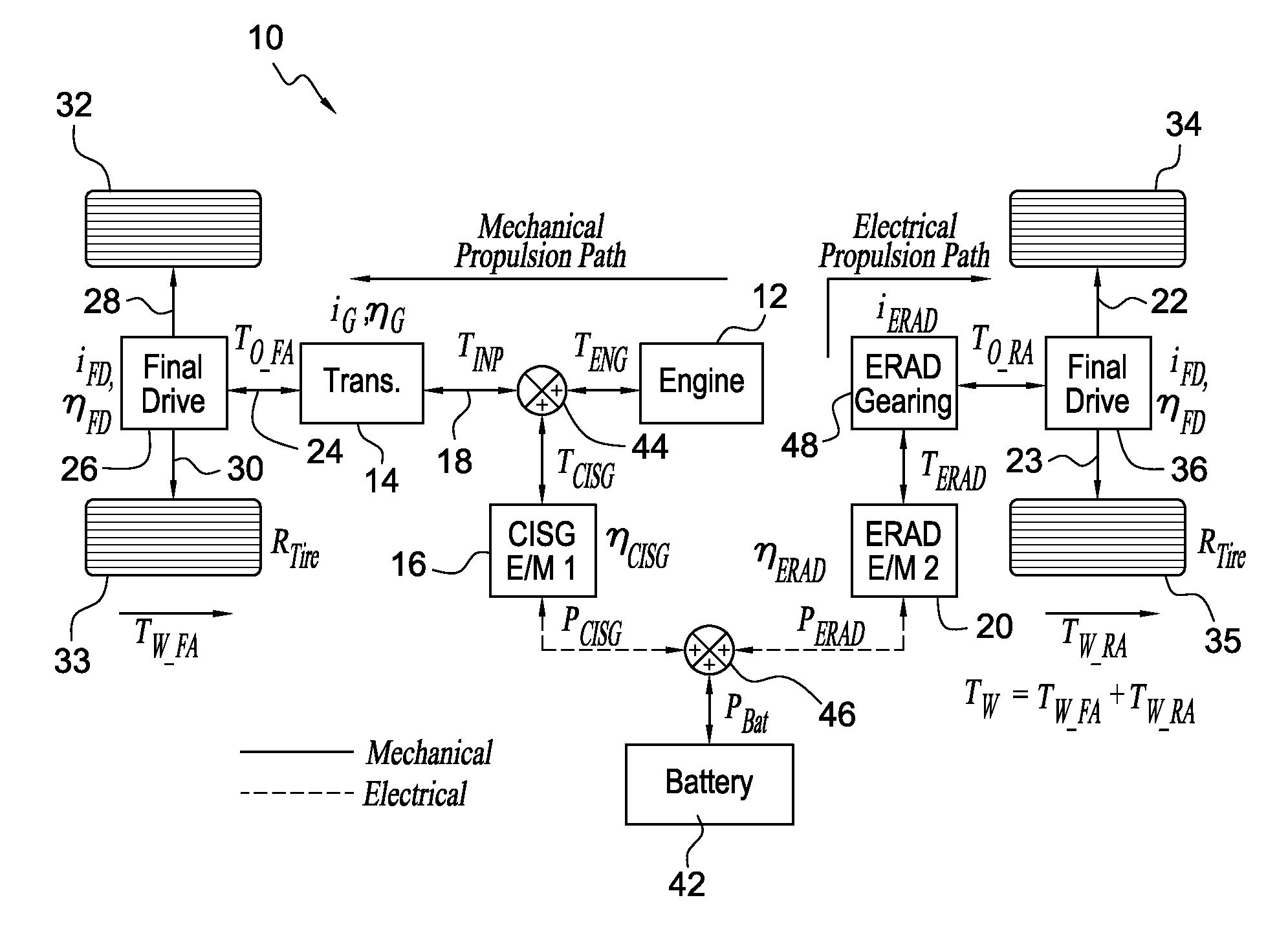
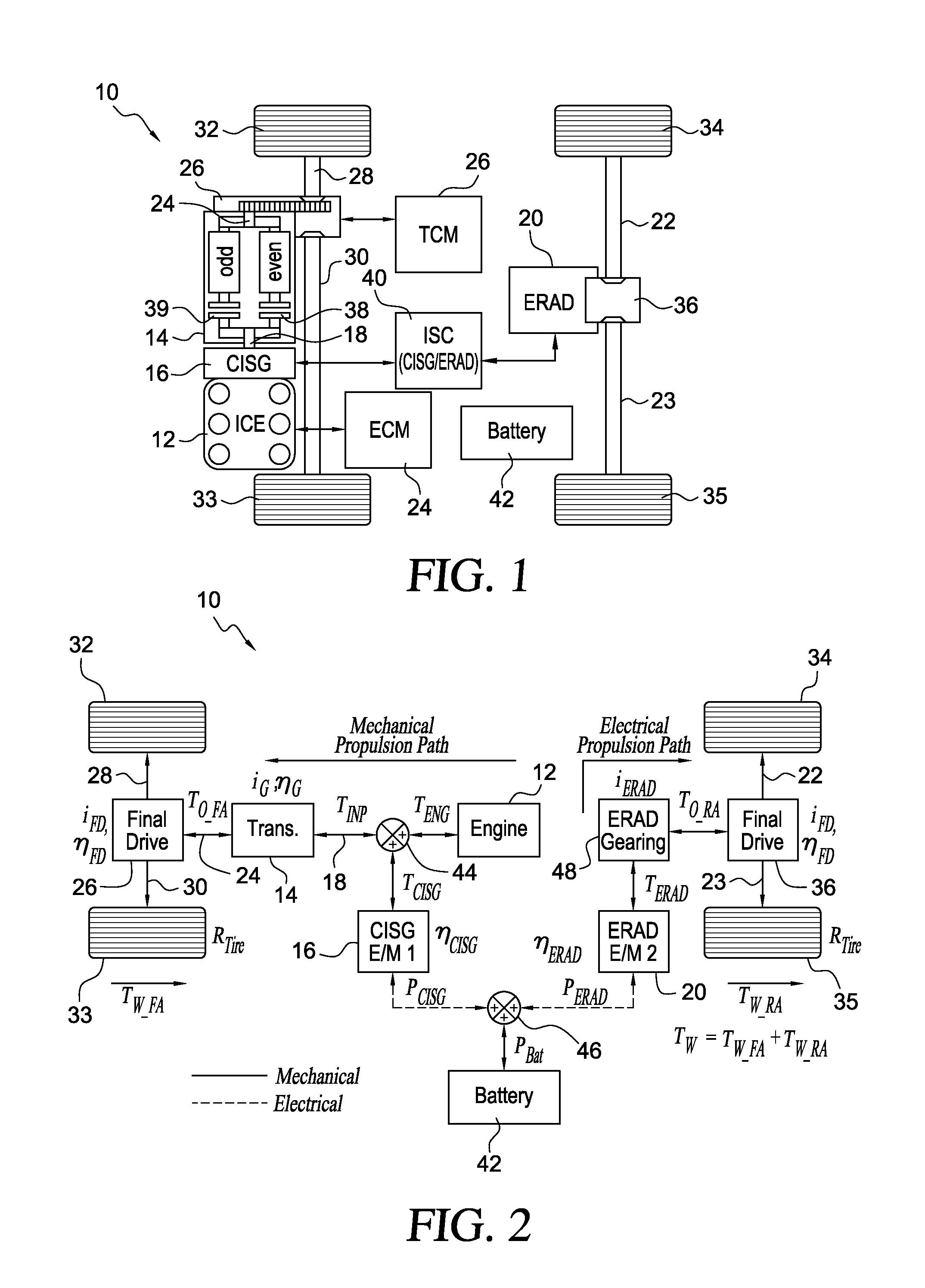
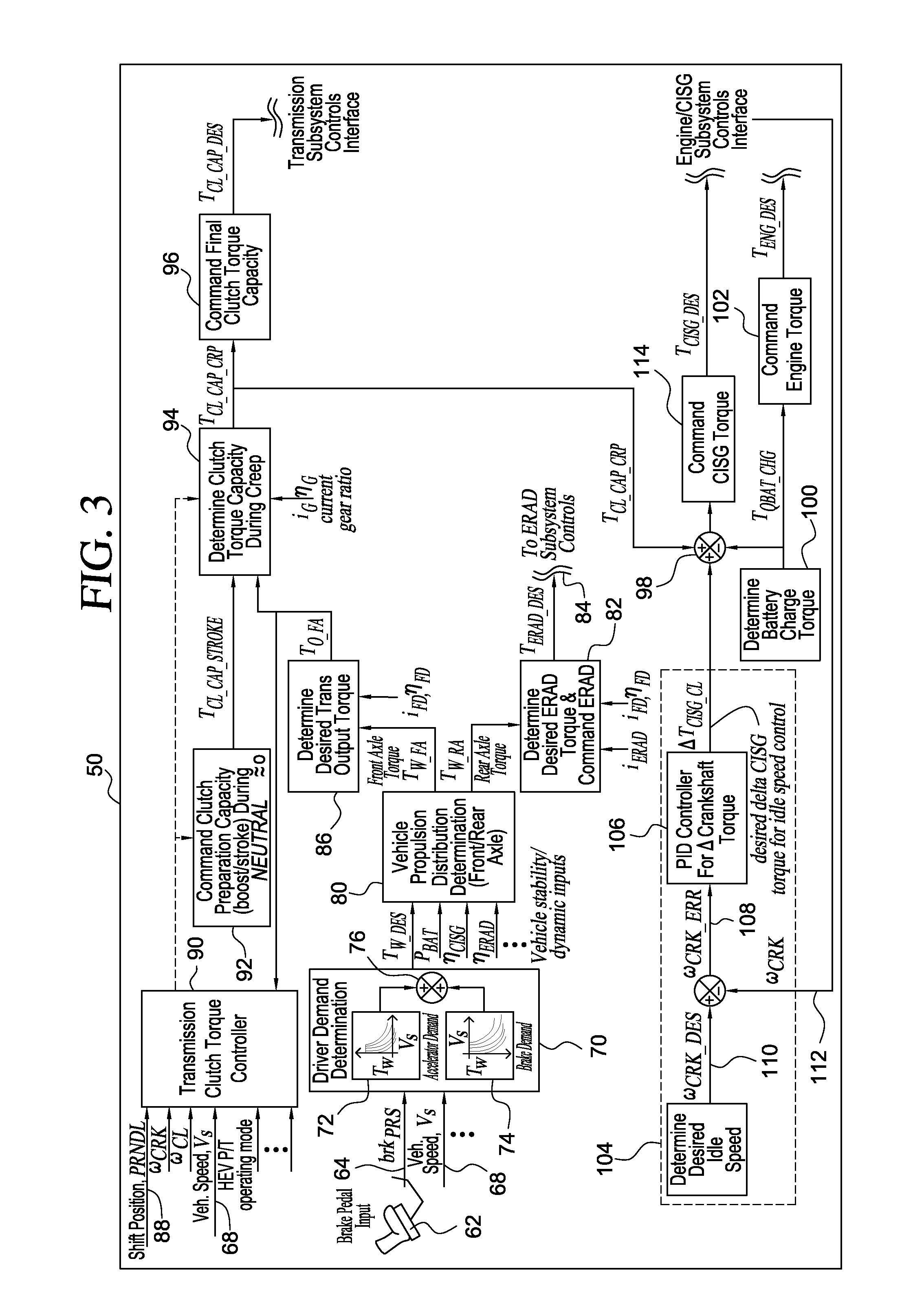
[0022]Referring first to FIGS. 1 and 2, the powertrain 10 configuration includes a first power source such as an internal combustion engine 12, a diesel engine or a gasoline engine; a power transmission 14 driveably for producing multiple forward and reverse gear ratios, such as a wet-clutch powershift transmission; an electric machine 16 driveably connected to the engine crankshaft and transmission input 18, such as a crankshaft integrated starter / generator (CISG) for providing starter / generator capability; and an additional electric machine 20 driveably connected to the rear axles 22,23, such as a electric rear axle drive (ERAD), for providing additional propulsion capability in either an electric drive or hybrid drive mode. The transmission output 24 is connected through a final drive unit and differential mechanism 26 to the front axles 28, 30, which drive the front wheels 32, 33, respectively. ERAD 20 drives the rear wheels 34, 35 through ERAD gearing 48, a differential mechani...


PUM


Abstract

In a powertrain that includes wheels for driving a vehicle, an engine including a crankshaft, a machine driveably connected to the crankshaft and able to operate alternately as an electric motor and electric generator, a transmission including an input clutch driveably connected to the crankshaft and an output driveably connected to at least two of the wheels, and an electric storage battery having a variable state of charge and electrically connected to the machine, a method for controlling vehicle creep including adjusting a torque capacity of the input clutch to a desired magnitude of input clutch torque transmitted to the wheels, determining a desired change in torque produced by the machine such that a speed of the crankshaft is controlled to a desired idle speed, using the magnitude of input clutch torque capacity and the desired change in torque produced by the machine to determine a desired magnitude machine torque, and using the machine to produce said desired magnitude of machine torque.

Description

BACKGROUND OF THE INVENTION[0001]1. Field of the Invention[0002]This invention relates generally to an apparatus and method for controlling vehicle creep in a hybrid electric vehicle (HEV).[0003]2. Description of the Prior Art[0004]A powershift transmission is a geared mechanism that includes no torque converter, but instead employs two input clutches driveably connected to an engine crankshaft. The transmission produces multiple gear ratios in forward and reverse drive and transmits power continuously using synchronized clutch-to-clutch shifts.[0005]The transmission incorporates gearing arranged in a dual layshaft configuration between the transmission input and its output. One input clutch transmits torque between the input and a first layshaft associated with even-numbered gears; the other input clutch transmits torque between the transmission input and a second layshaft associated with odd-numbered gears. The transmission produces gear ratio changes by alternately engaging a fir...

Claims


Application Information

Patent Timeline
Patent Type & Authority Applications(United States)
IPC IPC(8): B60W20/00B60W30/18
CPCB60K1/02Y10T477/75B60K6/547B60L2240/423B60L2240/486B60W10/02B60W10/06B60W10/08B60W20/00B60W30/18063B60W2710/027B60W2710/0644B60W2710/085B60W2710/105Y02T10/6265Y02T10/6286Y02T10/642Y02T10/7258B60K6/48B60W10/113Y02T10/6221Y10T477/26Y10T477/646B60K6/52Y02T10/62Y02T10/64Y02T10/72B60K6/36B60K6/38F16H3/728B60W2510/0275B60W2510/0642
Inventor SOLIMAN, IHAB S.SILVERI, ANDREW J.ASWANI, DEEPAK
Owner FORD GLOBAL TECH LLC
Why Eureka
Try Eureka