Wheel supporting device

Inactive Publication Date: 2009-04-16
JTEKT CORP
View PDF12 Cites 15 Cited by
  • Summary
  • Abstract
  • Description
  • Claims
  • Application Information

AI Technical Summary

Benefits of technology

[0042]In addition, it is possible to reduce the axial length of the wheel supporting device by the portion in which the calked portion at the end portion of the hub spindle is disused, thereby making it possible to attain weight saving.
[0043]Furthermore, the side face splines and the internal splines can be respectively formed easily by forging or the like on the end face and

Problems solved by technology

Moreover, if the hub wheel and the constant velocity joint are torque-transmittably coupled to each other by the meshing of the opposite side face splines on the end face of the hub spindle of the hub wheel and on the end face of the

Method used


Image

  • Wheel supporting device
  • Wheel supporting device
  • Wheel supporting device

Examples


first embodiment

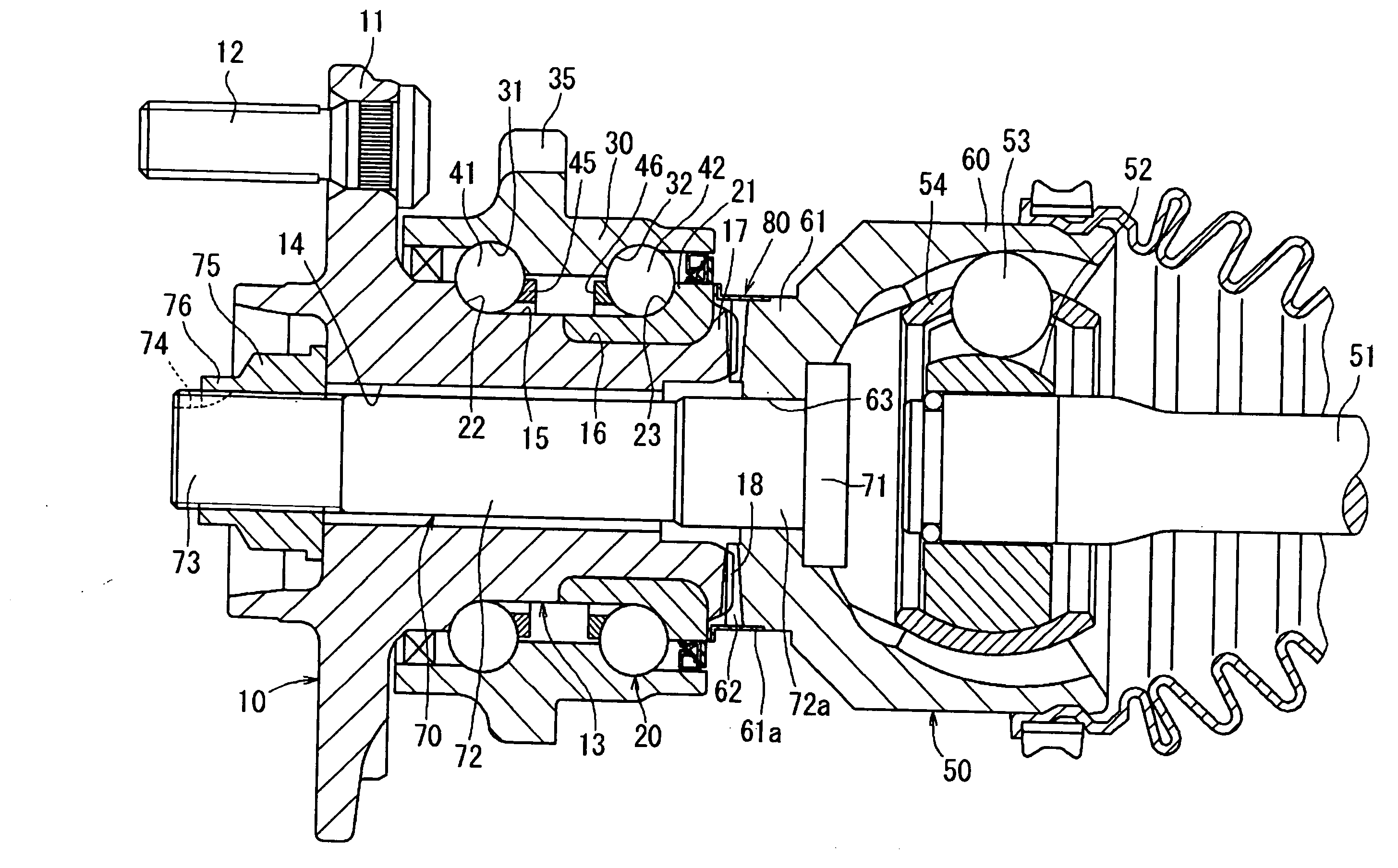
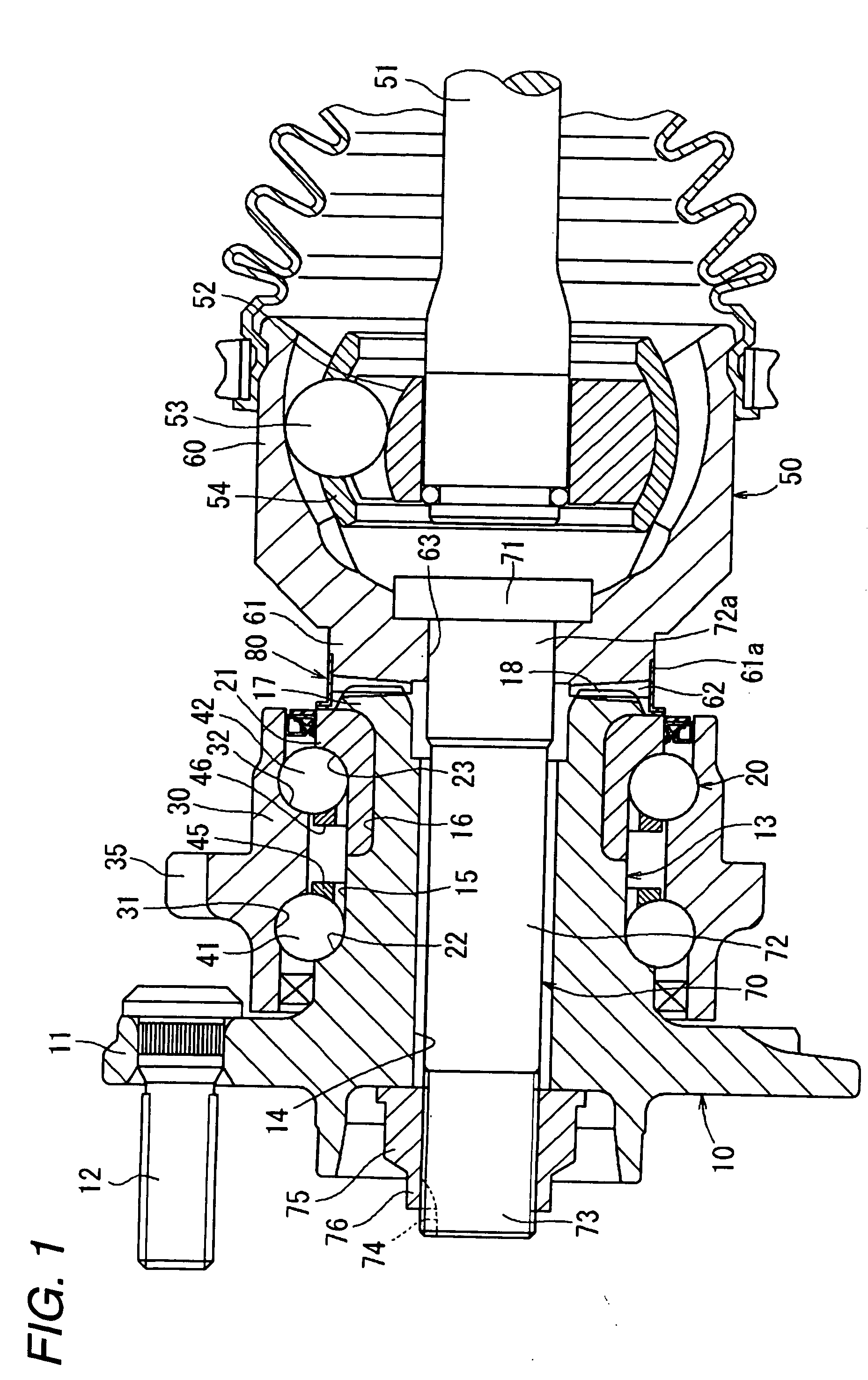
[0057]Referring to FIGS. 1 and 2, a description will be given of a first embodiment of the invention.

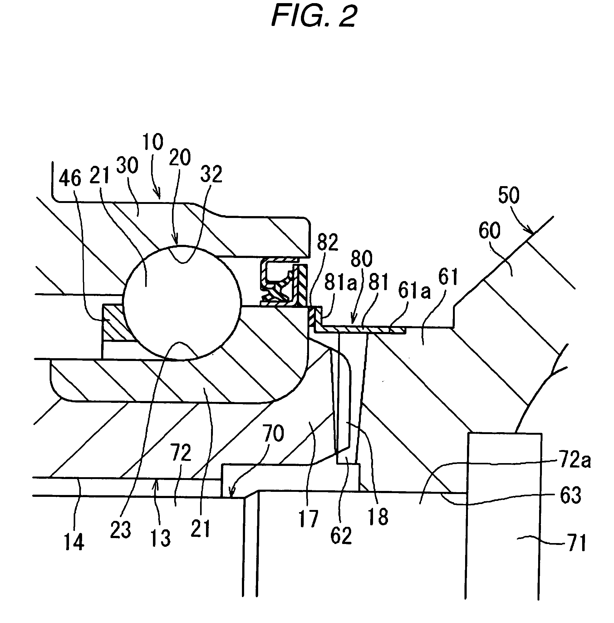
[0058]FIG. 1 is a side cross-sectional view illustrating a wheel supporting device in accordance with the first embodiment of the invention. FIG. 2 is a side cross-sectional view illustrating in enlarged form a state in which outer peripheries of opposite side face splines are covered by a tubular seal member disposed so as to straddle an inner ring of a rolling bearing of a hub spindle and an outer ring of a constant velocity joint.

[0059]As shown in FIG. 1, the wheel supporting device of this first embodiment is comprised of a hub wheel 10, a double row angular contact ball bearing 20 serving as a rolling bearing, a constant velocity joint 50, and a tubular seal member 80.

[0060]As shown in FIG. 1, the hub wheel 10 integrally has a cylindrical hub spindle 13 and a flange 11 formed on an outer peripheral surface of the hub spindle 13 close to one end portion thereof. Further, a plural...

second embodiment

[0088]Next, a description will be given of a second embodiment of the invention with reference to FIG. 3.

[0089]FIG. 3 is a side cross-sectional view illustrating in enlarged form a state in which a tubular seal member is disposed so as to straddle the inner ring of the rolling bearing of the wheel supporting device and the outer ring of the constant velocity joint in accordance with a second embodiment of the invention.

[0090]As shown in FIG. 3, a metal core 81, which constitutes a principal portion of a tubular seal member 180 which is disposed so as to straddle the inner ring 21 of the hub spindle 13 and the outer ring 60 of the constant velocity joint 50, is formed into a hollow cylindrical shape from a metallic material such as iron or stainless steel having a greater thickness than the metal core 81 of the first embodiment, and one end side thereof is pressed fitted and fixed to the outer peripheral surface of the side wall portion 61 of the constant velocity joint 50, while the...

third embodiment

[0097]Next, a description will be given of a third embodiment of the invention with reference to FIG. 4.

[0098]FIG. 4 is a side cross-sectional view illustrating in enlarged form a state in which a tubular seal member is disposed so as to straddle the inner ring of the rolling bearing of the wheel supporting device and the outer ring of the constant velocity joint in accordance with a third embodiment of the invention.

[0099]As shown in FIG. 4, a metal core 281, which constitutes a principal portion of a tubular seal member 280 which is disposed so as to straddle the inner ring 21 of the hub spindle 13 and the outer ring 60 of the constant velocity joint 50, is formed into a hollow cylindrical shape from a metallic material such as iron or stainless steel, and one end side thereof is pressed fitted and fixed to the outer peripheral surface of the inner ring 21 of the hub spindle 13, while the other end side thereof extends toward the outer ring 60 of the constant velocity joint 50.

[01...


PUM


Abstract

A rolling bearing is provided on an outer peripheral surface of a hub spindle of a hub wheel on which a wheel is mounted. Opposite side face splines, which, by meshing with each other, couple the hub spindle and an outer ring of a constant velocity joint torque-transmittably, are respectively formed on an end face of the hub spindle and on an end face of the outer ring of the constant velocity joint which is abutted against this end face. A tubular seal member for covering outer peripheries of the opposite side face splines is disposed so as to straddle an inner ring of the rolling bearing and the outer ring of the constant velocity joint, while maintaining a sealing state.

Description

BACKGROUND OF THE INVENTION[0001]1. Field of the Invention[0002]The present invention relates to a wheel supporting device in which a hub spindle of a hub wheel on which a wheel is mounted and an outer ring of a constant velocity joint are torque-transmittably coupled to each other.[0003]2. Related Art[0004]As a wheel supporting device of this type, a device is known in which a hub spindle of a hub wheel and an outer ring of a constant velocity joint are coupled by a coupling bolt, and opposite side face splines adapted to mesh with each other are respectively formed on an end face of the hub spindle of the hub wheel and on an end face of the constant velocity joint which is abutted against that end face. The hub wheel and the constant velocity joint are torque-transmittably coupled to each other by these opposite side face splines (e.g., refer to JP-A-63-184501).[0005]As a wheel supporting device of this type, a device is known in which, as shown in FIG. 12, to torque-transmittably...

Claims


Application Information

Patent Timeline
IPC IPC(8): F16C33/76
CPCB60B27/00F16C19/186F16C33/768F16C35/063F16C2326/02F16D1/076F16C2226/60F16D2003/22326F16C43/04B60B27/0005B60B27/0031B60B27/0042B60B27/0073F16D3/223
Inventor KAMIKAWA, TSUYOSHIKASHIWAGI, SHINICHIROU
Owner JTEKT CORP
Why Eureka
Try Eureka