Carbonitriding method, machinery component fabrication method, and machinery component

a technology of carbonitriding and machinery components, which is applied in the direction of manufacturing tools, furnaces, heat treatment equipment, etc., can solve the problems of increasing production costs, difficult to render the quality of the workpiece stable, and difficulty in directly measuring the amount of nitrogen permeating into the surface layer of the workpiece, so as to improve reduce the fabrication cost. , the effect of improving the nitrogen permeation ra

Active Publication Date: 2009-04-23
NTN CORP
View PDF1 Cites 2 Cited by
  • Summary
  • Abstract
  • Description
  • Claims
  • Application Information

AI Technical Summary

Benefits of technology

[0031]As apparent from the description set forth above, the present invention provides a carbonitriding method that improves the nitrogen permeating rate to render the carbonitriding process effective. Furthermore, by carrying out an effective carbonitriding process according to a machinery component fabrication method of the present invention, there can be provided a fabrication method of a machinery component, allowing the fabrication cost to be reduced. Moreover, by carrying out an effective carbonitriding process, a machinery component of the present invention, reduced in fabrication cost, can be provided.

Problems solved by technology

It is difficult to directly measure the amount of nitrogen permeating into the surface layer of the workpiece during the carbonitriding process.
It is therefore difficult to render the quality of the workpiece stable until the optimum ammonia gas flow rate is determined.
Moreover, since the trial and error must be carried out at the production line, workpieces that do not meet the required quality will be produced, leading to the possibility of increasing the production cost.

Method used


Image

  • Carbonitriding method, machinery component fabrication method, and machinery component
  • Carbonitriding method, machinery component fabrication method, and machinery component
  • Carbonitriding method, machinery component fabrication method, and machinery component

Examples


first embodiment

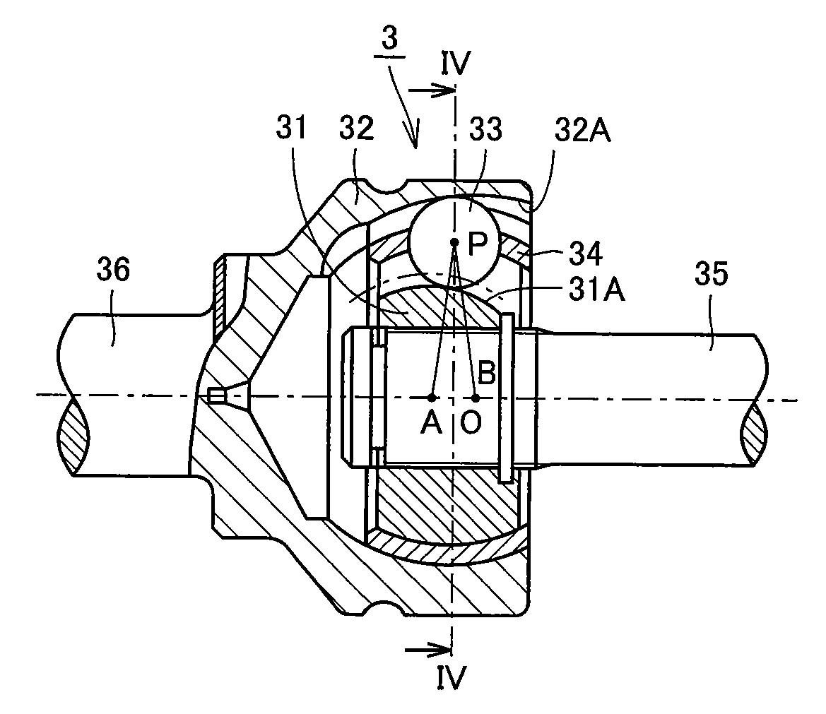
[0046]A deep groove ball bearing qualified as a rolling bearing according to a first embodiment of the present invention will be described hereinafter with reference to FIG. 1.

[0047]Referring to FIG. 1, a deep groove ball bearing 1 includes an annular outer ring 11, an annular inner ring 12 arranged at the inner side of outer ring 11, and a plurality of balls 13 serving as rolling elements arranged between outer and inner rings 11 and 12, held in a cage 14 of a circular ring configuration. An outer ring raceway 11 A is formed at the inner circumferential face of outer ring 11. An inner ring raceway 12A is formed at the outer circumferential face of inner ring 12. Outer ring 11 and inner ring 12 are disposed such that inner ring raceway 12A and outer ring raceway 11A face each other. The plurality of balls 13 are held in a rollable manner on the circular raceway, in contact with inner ring raceway 12A and outer ring raceway 11A, disposed at a predetermined pitch in the circumferentia...

second embodiment

[0092]A carbonitriding method, a machinery component fabrication method, and a machinery component according to a second embodiment of the present invention will be described hereinafter. The carbonitriding method, machinery component fabrication method, and machinery component of the second embodiment are basically similar in configuration to the carbonitriding method, machinery component fabrication method, and machinery component of the first embodiment set forth above, and provides similar advantages. The second embodiment differs from the first embodiment in that atmosphere control step 50 in the carbonitriding method is carried out as set forth below.

[0093]Referring to FIG. 7, in atmosphere control step 50, undecomposed NH3 partial pressure control step 51, CO / CO2 partial pressure control step 53, and H2 partial pressure control step 52 are executed such that EN defined by equation (3) is at least 7.5.

[0094]Specifically, in CO / CO2 partial pressure control step 53, the supplied...

example 1

Example 1 of the present invention will be described hereinafter. An experiment to study the relationship of the γ value and the hydrogen partial pressure in the heat treatment furnace to the permeating amount of nitrogen into the workpiece was carried out. The procedure of the experiment is set forth below.

[0102]The capacity of the heat treatment furnace employed for the experiment was 120 L (liter). The workpiece was a JIS SUJ2 (1 mass % of carbon content) ring having an outer diameter of 38 mm, an inner diameter of 30 mm, and a width of 10 mm. This ring of 101 g (gram) was placed in the heat treatment furnace. A heating pattern similar to that of FIG. 10 was employed, and the retention temperature of carbonitriding was 850° C. The carbonitriding time was 9000 seconds, and the flow rate of the base gas (the atmosphere gas other than enriched gas and ammonia gas) supplied into the heat treatment furnace was 11.5 L / min. under the atmospheric pressure of 1.05 at 20° C. The permeating...


PUM

PropertyMeasurementUnit
temperatureaaaaaaaaaa

Abstract

A carbonitriding method that can improve the nitrogen permeating rate to render the carbonitriding process effective is directed to carbonitriding a workpiece formed of steel that contains at least 0.8 mass % of carbon by heating in an atmosphere including ammonia, carbon monoxide, carbon dioxide and hydrogen. The method includes an atmosphere control step (50), and a heating pattern control step (60). The atmosphere control step (50) includes an undecomposed NH3 partial pressure control step (51), a CO / CO2 partial pressure control step (53), and an H2 partial pressure control step (52). The undecomposed NH3 partial pressure control step (51), the CO / CO2 partial pressure control step (53) and the H2 partial pressure control step (52) are carried out such that the partial pressure of hydrogen in the heat treatment furnace is at least 0.1 atmospheric pressure and not more than 0.3 atmospheric pressure, and γ defined by the following equation (1) is at least 2.0 and not more than 6.0, in the atmosphere control step (50).γ=ac*CNH3(1)whereac*=(Pco)2K×Pco2(2)PCO: partial pressure of carbon monoxide (atm); PCO<sub2>2< / sub2>: partial pressure of carbon dioxide (atm),K: equilibrium constant at <C>+CO2 2CO;CNH<sub2>3< / sub2>: undecomposed ammonia concentration (volume %)

Description

TECHNICAL FIELD[0001]The present invention relates to a carbonitriding method, a fabrication method of a machinery component, and a machinery component. More particularly, the present invention relates to a carbonitriding method for carbonitriding a workpiece formed of steel that contains at least 0.8 mass % of carbon, a fabrication method of a machinery component including the step of carbonitriding a workpiece formed of steel that contains at least 0.8 mass % of carbon, and a machinery component formed of steel that contains at least 0.8 mass % of carbon, subjected to carbonitriding.BACKGROUND ART[0002]Generally in a carbonitriding process, particularly in a gas carbonitriding process applied to a workpiece formed of steel, the atmosphere in a heat treatment furnace is controlled by introducing RX gas and ammonia (NH3) gas into the heat treatment furnace at a constant flow rate (supplied amount per unit time), and controlling the carbon potential (CP) value in the heat treatment f...

Claims


Application Information

Patent Timeline
Patent Type & Authority Applications(United States)
IPC IPC(8): C23C8/32
CPCC21D1/06C21D1/18C21D1/74C23C8/32C21D9/40C21D11/00C21D1/76
Inventor OHKI, CHIKARA
Owner NTN CORP
Why Eureka
Try Eureka