Turbo-guiding type cooling apparatus

a cooling apparatus and guiding technology, applied in lighting, heating apparatus, instruments, etc., can solve the problems of reducing the volume of heat removal and saving precious, and achieve the effect of smooth air delivery, enhancing heat removal efficiency, and smooth removal of heat energy

Inactive Publication Date: 2009-04-23
CHENG LIANG HO
View PDF12 Cites 23 Cited by
  • Summary
  • Abstract
  • Description
  • Claims
  • Application Information

AI Technical Summary

Benefits of technology

[0011]A primary object of the invention is to provide a turbo-guiding type cooling apparatus that smoothly delivers the current of air generated by a fan to a heat sink such that a heat exchange takes place in a heat region where t

Problems solved by technology

Moreover, the heat-removal volume is

Method used


Image

  • Turbo-guiding type cooling apparatus
  • Turbo-guiding type cooling apparatus
  • Turbo-guiding type cooling apparatus

Examples


Embodiment Construction

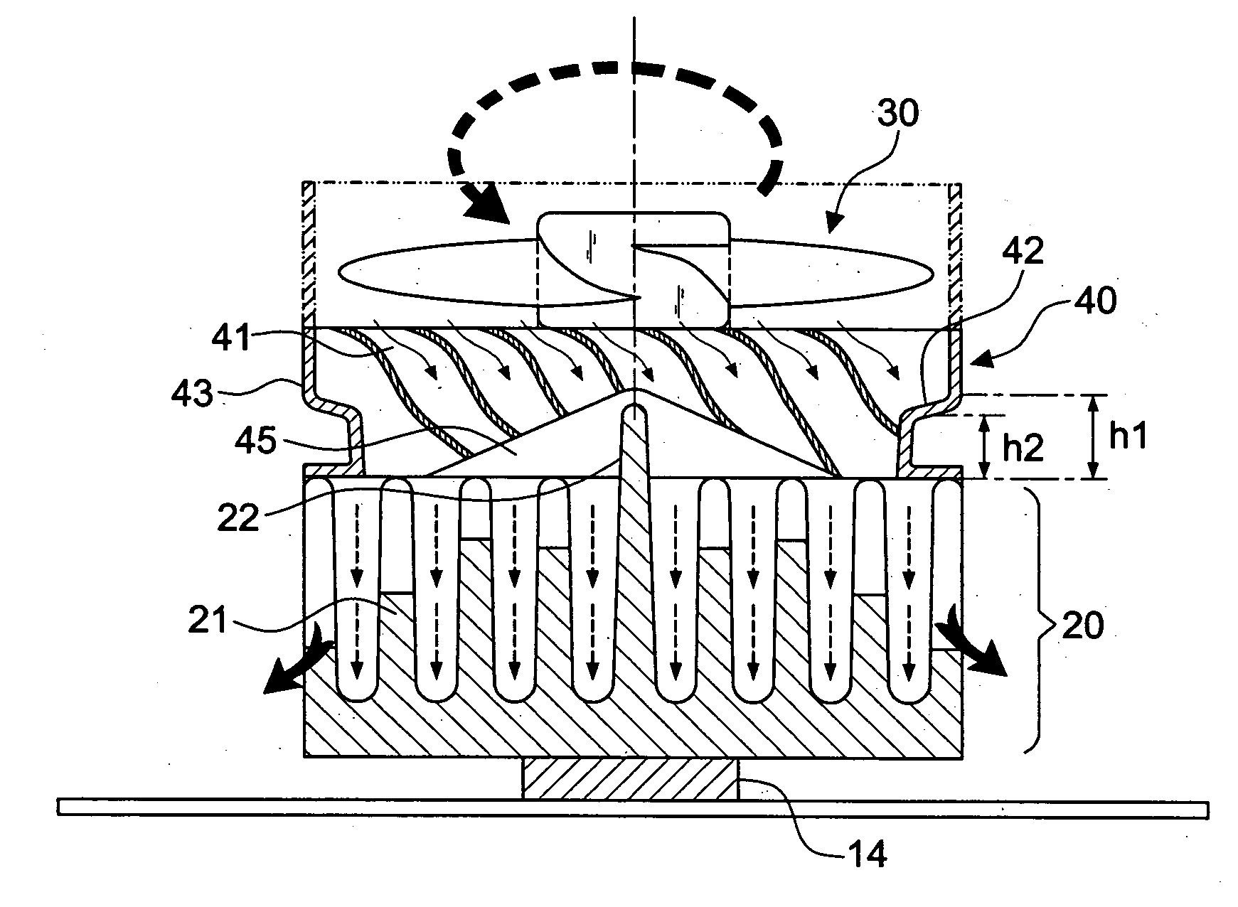
[0048]First of all, referring to FIGS. 6 and 7, a turbo-guiding type cooling apparatus in accordance with the invention includes a heat sink 20, and a fan 30.

[0049]The heat sink 20 includes a plurality of horizontal type cooling fins 21. According to the embodiment, the heat sink 20 belongs to a horizontal type heat sink. It should not be restricted thereto. The configuration of the invention can be also applied to the vertical type heat sink or heat-conducting module. These will be described in detail hereinafter. The heat sink 20 is not the object of the invention so that no further descriptions thereto are given hereinafter.

[0050]The fan 30 is disposed at the top of the heat sink 20. According to the invention, the fan 30 is an axial-flow fan so that the heat exchange takes place by delivering cool air downward to the heat sink 20.

[0051]The invention features a reverse fixed blade unit 40 interposed between the wind exit surface of the fan 30 and the heat sink 20. The rotation di...


PUM


Abstract

A turbo-guiding type cooling apparatus includes a reverse fixed blade unit interposed between the wind exit surface of the fan and the heat sink. The rotation direction of the reverse fixed blade unit is opposite to that of the fan. A receiving chamber is formed under the shaft of the reverse fixed blade unit, and the receiving chamber has at least one-third height of the reverse fixed blade unit. A separation portion extending into the receiving chamber is formed at the center of the top of at least one part of the heat sink. The reverse fixed blade unit includes a reduction cover inward tapered at the periphery of the wind outlet thereof. The height (h1) of the periphery of the reduction cover is the same to or greater than the height (h2) of the periphery of the wind outlet of the reverse fixed blade unit, thereby forming a ring-shaped enclosing type. Therefore, the wind will be smoothly concentrated and the flow direction will be changed. Meanwhile, each of the airflows will be separated by the separation portion and delivered to the heat source of the heat sink.

Description

BACKGROUND OF THE INVENTION[0001]1. Field of the Invention[0002]The invention relates to a turbo-guiding type cooling apparatus, and more particularly to a structure that includes a reverse fixed blade unit and a reduction cover between a heat sink and a fan.[0003]2. Description of the Related Art[0004]As shown in FIGS. 1 and 2, a conventional cooling apparatus 10 applied to CPU or other electronic chips includes a heat sink 11 having a plurality of fins and an axial flow fan 12 disposed at the top of the heat sink 11. The bottom of the heat sink 11 lies on the surface of the electronic chip (or heat source 14). After the operation of the fan 12, the heat energy of the heat source 14 can be transmitted to all fins of the heat sink 11 by use of the heat conduction. Meanwhile, the cool air generated by the fan 12 is delivered to the fins of the heat sink 11 for conducting the heat exchange. In the way, the heat energy is removed.[0005]However, the conventional fan 12 belongs to an axi...

Claims


Application Information

Patent Timeline
IPC IPC(8): F28D15/00
CPCH01L23/467H01L2924/0002H01L2924/00F04D29/582F04D29/542F04D19/002F04D29/547G06F1/20H05K7/20
Inventor CHENG, LIANG-HO
Owner CHENG LIANG HO
Why Eureka
Try Eureka