Wellhead flowline protection and testing system with ESP speed controller and emergency isolation valve

a technology of speed controller and flowline protection, which is applied in the direction of survey, instruments, borehole/well accessories, etc., can solve the problems of impracticality, insufficient pressure rating of flowline network suited for normal operations, and high pressure build-up in the piping network to the pump's fully-blocked discharge pressure, etc., to reduce the burden on operations and maintenance personnel

Active Publication Date: 2009-04-23
SAUDI ARABIAN OIL CO
View PDF5 Cites 38 Cited by
  • Summary
  • Abstract
  • Description
  • Claims
  • Application Information

AI Technical Summary

Benefits of technology

[0033]Should a fault be detected with the valve, pump speed controller, or sensors, personnel are alerted and can take appropriate steps to perform the required maintenance without an adverse impact on safety or operations. Most importantly, the invention provides a safety instrument system (SIS) for a HIPS that can be completely tested without interrupting the oil/gas production through the flowline during the test protocol and that can respond immediately to shut down the ESP and SSV, should that become necessary.
[0034]The system of the invention is preferably factory built and tested, and can be skid-mounted with flange connections on the input and output of the flow piping system for ease of modular installation in the field. The consistent use of the same desi

Problems solved by technology

One problem that the new downhole ESP production controller introduced was that although it provided the required pressure boost to keep the oil flowing, should an intermediate block valve close in the long network of flowlines and trunklines between an offshore production platform and the onshore GOSP, the pressure would build in the piping network to the pump's fully-blocked discharge pressure which is much higher than the normal flowing pipeline pressure.
A flowline n

Method used


Image

  • Wellhead flowline protection and testing system with ESP speed controller and emergency isolation valve
  • Wellhead flowline protection and testing system with ESP speed controller and emergency isolation valve

Examples


Embodiment Construction

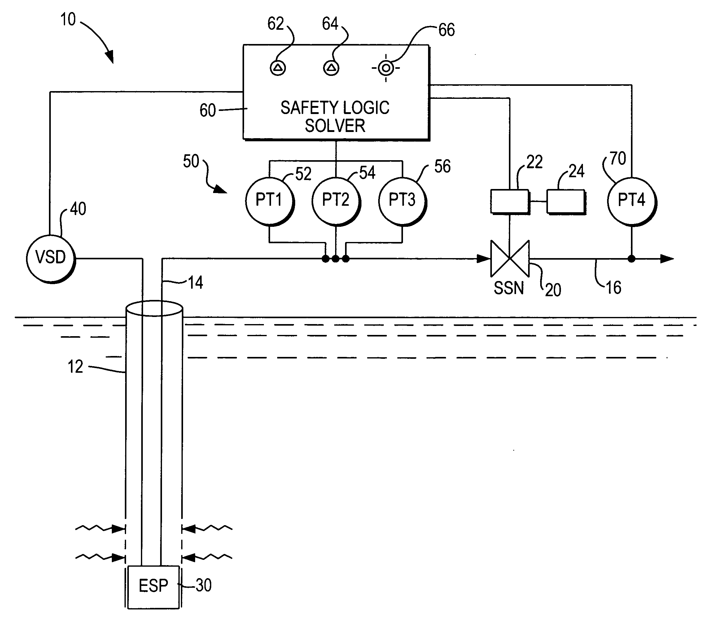
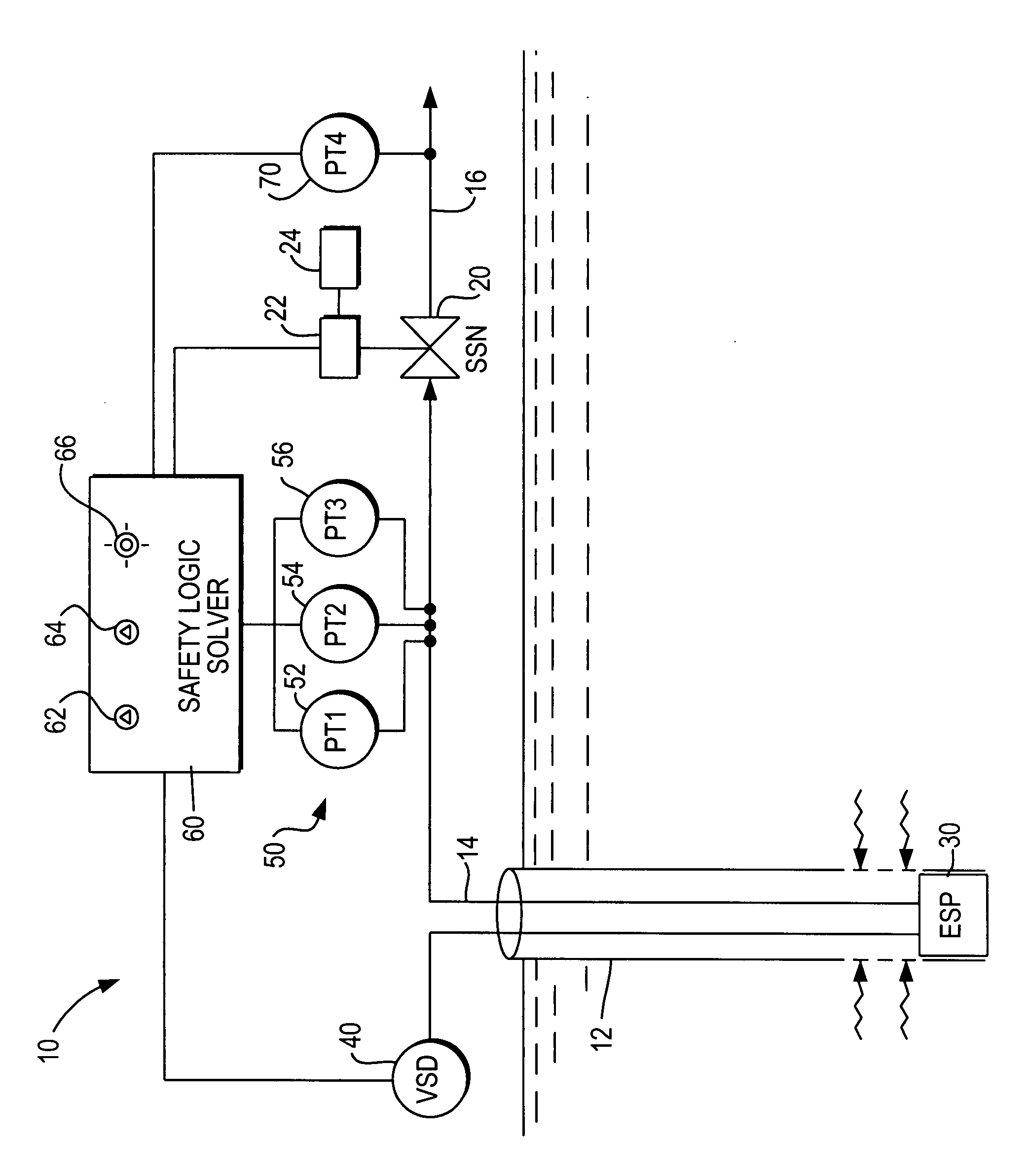
[0037]The invention will be further described with reference to the attached drawing which depicts a wellbore casing 12 from which extends a production tubing 14 that is constructed from a high pressure rated piping that terminates at surface safety shut-off valve 20. Downstream of the SSV 20, conventional piping 16 rated for a lower pressure is installed for the transportation and distribution of the product.

[0038]The downhole end of production tubing 14 is attached to electric submersible pump 30 which delivers the pressurized stream of reservoir gas and / or oil for eventual transportation and distribution through the downstream flowline piping network. In accordance with the invention, a variable speed drive controller 40 is operatively connected to downhole pump 30 and also to safety logic solver 60.

[0039]A plurality of pressure transmitting sensors 50 are installed on the high pressure rated flowline piping 14 and are in data communication with safety logic solver 60. In the emb...


PUM


Abstract

An ESP variable speed drive controller functions in conjunction with a safety logic solver, dedicated pressure sensors and a surface emergency isolation valve, or safety shut-off valve (SSV), to perform a full functional test of the complete wellhead flowline system. The method includes the step of using a plurality of pressure transmitters to monitor the flowline pressure during normal operations and during a full stroke test of the safety shutoff valve and adjusting the speed of the downhole ESP during the test to maintain the pipeline pressure within predetermined safe pressure limits. This wellhead flowline protection system and method utilizes the downhole ESP speed controller and an SSV to ensure that dangerous pressure levels are not reached and provides for full functional safety testing of the wellhead system. The ESP motor speed controller is used to permit functional testing and remove the pressure source from protected downstream flowline piping.

Description

FIELD OF THE INVENTION[0001]This invention relates to a protection system for a wellhead piping flowline that is pressurized by a downhole electric submersible pump (ESP) to protect downstream low pressure rated transportation and distribution pipelines, and that also provides a fully-automated safety and fault test function.BACKGROUND OF THE INVENTION[0002]A wellhead high integrity protection system (HIPS) protects flowlines connected to a wellhead from overpressure should a downstream block valve close. The pressure source can be the oil-bearing geologic formation pressure. This pressure is known as the wellhead shut in pressure and it is based on geologic parameters, it is continuous, it cannot be controlled. i.e. it cannot be “turned off” in the conventional sense of that term. Multiple automated block valves are required in series downstream of the wellhead pressure source so that in case one valve leaks or fails to close, another will function to do so.[0003]Although the surfa...

Claims


Application Information

Patent Timeline
IPC IPC(8): E21B44/06
CPCE21B47/0007E21B43/128E21B43/00E21B47/008E21B47/117
Inventor FLANDERS, PATRICK S.
Owner SAUDI ARABIAN OIL CO
Why Eureka
Try Eureka