Wavelength measurement system

a wavelength measurement and wavelength technology, applied in the field of fiber optic sensing systems, can solve the problems of limited practical application, wavelength errors, wavelength errors, etc., and achieve the effects of stable, very repeatable, and high-speed fbg interrogation

Active Publication Date: 2009-04-23
AVALON SCI
View PDF2 Cites 33 Cited by
  • Summary
  • Abstract
  • Description
  • Claims
  • Application Information

AI Technical Summary

Benefits of technology

[0012]The present invention mitigates the above-mentioned problems to ensure very stable, very repeatable, high-speed FBG interrogation without the need for periodic recalibration. The interrogator comprises a broadband optical source, at least one beam splitter directing output of the optical source to an array of fiber optic gratings, at least one linear transmission or reflection filter, at least one optical receiver and at least one amplifier associated with each receiver. In one aspect of the invention, a linear transmission filter is used to convert the change in center wavelength of a grating reflectivity spectrum to a change in intensity, which is proportional to the change in the grating central wavelength. In another aspect of the invention, a pair of opposite-sloped linear transmission filters are utilized to normalize the received and filtered reflections with respect to total optical power. In another aspect of the invention, the optical source is pulsed, and return pulses from each fiber optic grating to be measured are sampled by the interrogator at different times. In another aspect of the invention, the source driver randomizes ripple phase versus wavelength to reduce wavelength measurement error. In another aspect of the invention, active closed-loop circuits are added to the receiver amplifiers to stabilize the amplifier output. In yet another aspect of the invention, a temperature-controlled compensating array of fiber optic gratings is interrogated each time the measurement array of gratings is interrogated. In still another aspect of the invention, a fast reset analog integrator is added to the amplifier stage(s) to improve the signal detection threshold. In another aspect of the invention, the wavelength measurement is compensated for the effects of one grating shading another.

Problems solved by technology

However, the prior art approaches have several shortcomings that render their usefulness limited for practical applications.
Wavelength errors due to stable optical source ripple phase
Susceptibility to intensity and spectrum changes in components that can cause wavelength errors
Susceptibility to power supply noise
Wavelength errors due to low frequency receiver output drift
Errors due to multi-FBG source spectrum masking
Wavelength uncertainty due to low signal-to-noise resulting from very short analog-to-digital conversion times.

Method used


Image

  • Wavelength measurement system
  • Wavelength measurement system
  • Wavelength measurement system

Examples


Embodiment Construction

[0018]In the following description, for purposes of explanation and not limitation, specific details are set forth in order to provide a thorough understanding of the present invention. However, it will be apparent to one skilled in the art that the present invention may be practiced in other embodiments that depart from these specific details. In other instances, detailed descriptions of well-known methods and devices are omitted so as to not obscure the description of the present invention with unnecessary detail.

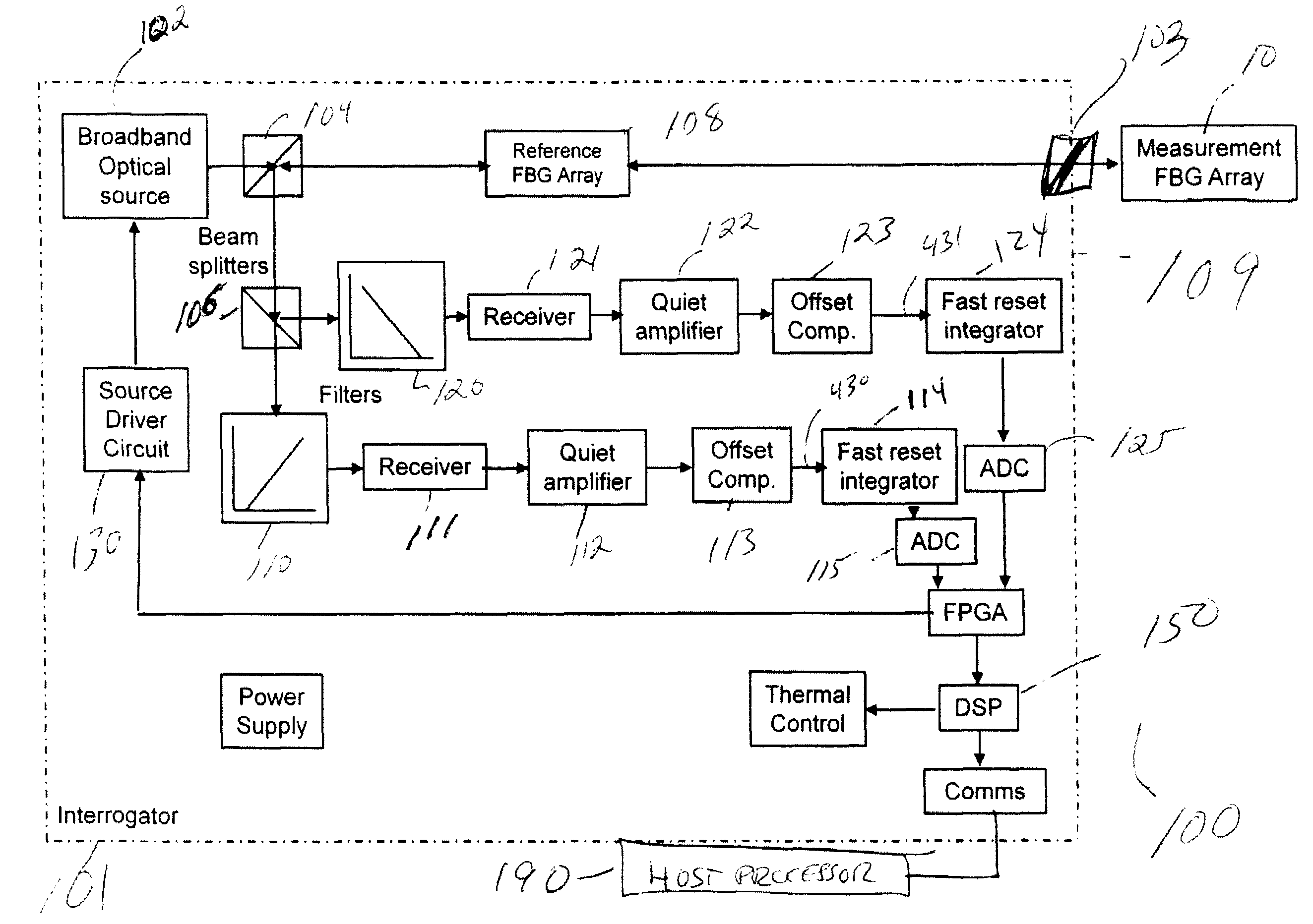
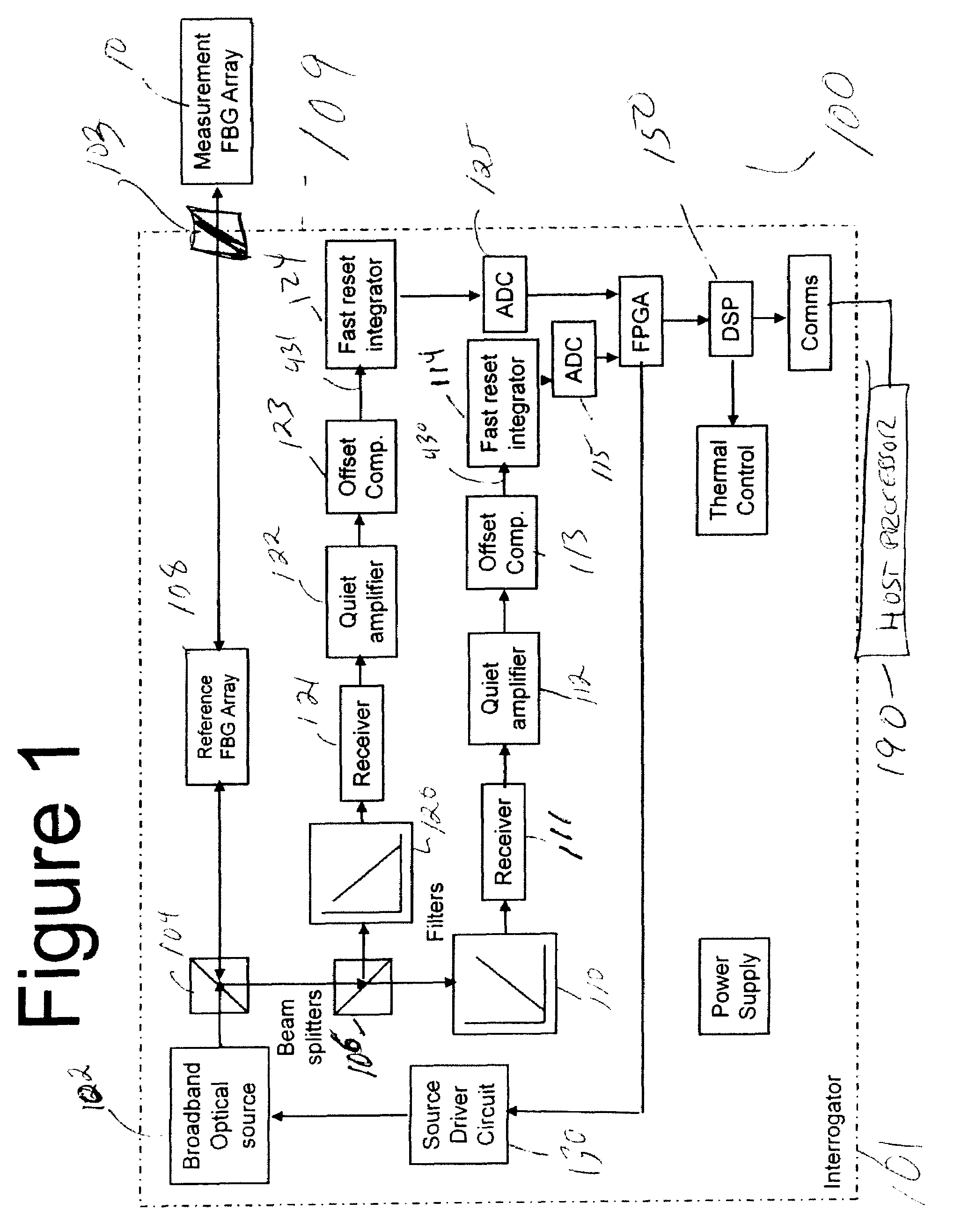
[0019]An exemplary sensor interrogation system 100 embodying the present invention is shown in FIG. 1. In many respects, this system follows practices of prior art FBG interrogators as shown by earlier patents and in the open literature. Fundamentally, the interrogator illuminates an array of FBGs 10 with a broadband optical source 102 (LED, ELED, SLD, SLED, ASE source, SOA, etc.) through a first optical beam splitter 104 (bulk optic type, or a fiber optic coupler or fibe...


PUM


Abstract

A fiber optic interrogator includes a broadband optical source, at least one beam splitter directing output of the optical source to an array of fiber optic gratings, at least one linear transmission or reflection filter, at least one optical receiver and at least one amplifier associated with each receiver. In one aspect of the invention, a linear transmission filter is used to convert the change in center wavelength of a grating reflectivity spectrum to a change in intensity, which is proportional to the change in the grating central wavelength. In another aspect of the invention, a pair of opposite-sloped linear transmission filters are utilized to normalize the received and filtered reflections with respect to total optical power. In another aspect of the invention, the optical source is pulsed, and return pulses from each fiber optic grating to be measured are sampled by the interrogator at different times. In another aspect of the invention, the source driver randomizes ripple phase versus wavelength to reduce wavelength measurement error. In another aspect of the invention, active closed-loop circuits are added to the receiver amplifiers to stabilize the amplifier output. In yet another aspect of the invention, a temperature-controlled compensating array of fiber optic gratings is interrogated each time the measurement array of gratings is interrogated. In still another aspect of the invention, a fast reset analog integrator is added to the amplifier stage(s) to improve the signal detection threshold. In another aspect of the invention, the wavelength measurement is compensated for the effects of one grating shading another.

Description

CROSS-REFERENCE TO RELATED APPLICATION[0001]This application claims priority of provisional application No. 61 / 000,257 filed Oct. 23, 2007.FIELD OF THE INVENTION[0002]This invention relates generally to the field of fiber optic sensing systems and, more particularly, to an improved method and apparatus for accurately measuring the center wavelength of the reflection spectrum of a fiber optic grating.BACKGROUND OF THE INVENTION[0003]Fiber Bragg gratings (FBGs) are commonly used in fiber optic systems for measuring physical quantities such as temperature, pressure and strain at a plurality of sensors. A number of different approaches have been used for the interrogation of FBGs, that is, for determining the center wavelength of the reflection spectrum of each FBG. However, the prior art approaches have several shortcomings that render their usefulness limited for practical applications. Some of these shortcomings include:[0004]Limited number of FBGs that can be interrogated along a si...

Claims


Application Information

Patent Timeline
Patent Type & Authority Applications(United States)
IPC IPC(8): G02B6/00H01J43/00
CPCG01D5/35383H04J14/02G01M11/30H04J14/0204G01J1/0407H04J14/0201G01D5/35316G01D5/3539
Inventor GOLDNER, ERIC LEEBAKER, GERALD ROBERT
Owner AVALON SCI
Why Eureka
Try Eureka