Stereoprojection system

a projection system and stereoscope technology, applied in the field of stereoscope projection systems, can solve the problems of small disadvantage of prototypes, auto-correction and video correction of stereoimages, and inconvenience of long viewing of stereoimages, and achieve the effects of avoiding eye and brain irritation and weariness causing psychical disorders, high contrast, and high resolution

Inactive Publication Date: 2009-04-23
ARSENICH SVYATOSLAV IVANOVICH
View PDF6 Cites 96 Cited by
  • Summary
  • Abstract
  • Description
  • Claims
  • Application Information

AI Technical Summary

Benefits of technology

[0009]The principal object of the invention is to provide full comfort stereoscopic projection systems for individual and collective stereoscopic viewing without conventional stereoscopic glasses. Another object of the invention is to create a full comfort projection system with stereoscopic glasses allowing free eye accommodation without auxiliary optical stereoscopic systems on the stereoscreens located close to the eyes and in projection reflecting spherical stereoscopic glasses (stereoscreens). Full comfort of stereoscopic vision is a combination of physical, physiological and visual comfort of a viewer without limitation of stereoscopic viewing time in conditions of external flare light on the stereoscreen. Physical comfort envisages free movement of the viewer in a spacious viewing zone, inclination and turn of the viewer's head and body, movement of the eyes and pupils (convergence of the visual axes to the ocular focal point). Physiological comfort causes psychomotor reactions: feeling of visual depth and presence effect—perception of movements and real spatial depth of the objects' images by a viewer. At the same time irritation and weariness of eyes and brains causing psychical disorders are avoided. Visual comfort—provision of stereoviewing of the screen stereoimages of standard quality (with high brightness of up to 3000 cd / m2 and high contrast of about 1000 units in conditions of direct solar illumination, with high resolution and clearness without geometrical distortions), with feeling of high depth of stereo effect, approaching binocular observing of the real objects. The stereoimage shall be wide-framed with horizontal angle of field of vision of 70° and vertical angle of field of vision of 50°; this increases depth of stereo effect and reduces the pushing border effect when the screen border cuts a part of the image.

Problems solved by technology

The known countertypes of the stereoscopic projection systems (golographic, raster, with stereoscopic glasses, retroreflective and others) with the exception of the system of projection on reflecting spherical stereoscreens are discomfort and unfit for long viewing of stereoimages.
The common drawback of these countertypes is a technical problem of auto-correction and video correction of the stereoscopic system individually for each viewer.
The prototype's disadvantage is small and limited improvement of the stereoscopic comfort.
Different curvature of the left and right frames of the stereopair images increases feeling of stereoscopic discomfort, strain and weariness of the eyes because this increases visible divarication of the conjugate points (any two points of the stereopair left and right frames observed as a single point of the stereoimage) as the eyes focal point moves to the stereoscreen border.
The prototype disadvantages result from the fact that only auto-corrector and automatic drives are used for auto-correction of displacement of the stereoscopic projection lenses relative to the stereoscreen.

Method used


Image

  • Stereoprojection system
  • Stereoprojection system
  • Stereoprojection system

Examples


Embodiment Construction

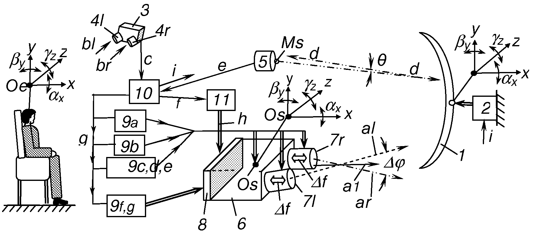
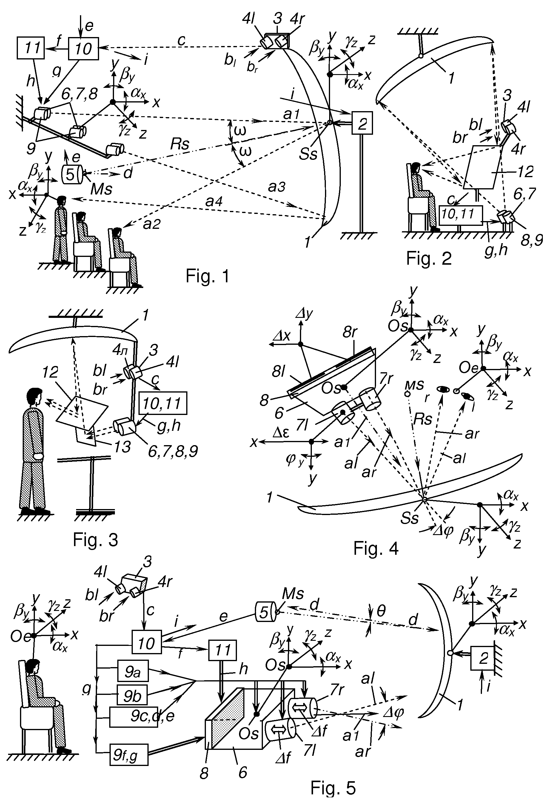
[0070]FIG. 1 shows a stereoscopic projection system intended for cinema, theaters, video theaters, concert halls, studios, gymnasia, conference rooms, and other video halls with a large number of viewers (50-500 persons). A big reflecting spherical stereoscreen 1 with surface of 10-100 m2 and mirror sphere radius Rs (10-40 m) is fast mounted on the auto-drives 2. Ss—an apex of the stereoscreen reflecting sphere radius. Ms—programmed center of the stereoscreen reflecting sphere, Rs—radius of this sphere, Ss—pole of this sphere. Above the stereoscreen on a hanged bracket a tracking system 3 is mounted with left 4l and right 4r video cameras for monitoring of the viewers' eyes position. In the point Ms an auto-collimator 5 is mounted for monitoring of orientation of the stereoscreen reflecting sphere. In front of the stereoscreen above the viewers stereoprojectors 6 are mounted (one for each viewer) with movable projection lenses 7, projections units 8 for forming the projected stereop...


PUM


Abstract

The invention relates to stereo projection systems for displaying stereopaired images on mirror-spherical or parabolic screens and for collectively watching a stereo effect without using stereo spectacles. Said invention makes it possible to continuously dynamically superimpose the projections of the left and right picture frames of a steropair with the user's left and right eyes, respectively. Such impositions are carried out simultaneously and independently for each viewer. The technical result is attainable by that the inventive stereo projection system comprises stereo projectors which are individually allocated to each viewer and in-series connected, a monitoring system for continuously and accurately determining the viewers' eye positions, a self correcting device, video-correcting devices, automatic drives for the mechanical self-correction of the stereo projectors and the system optical elements, units which are used for forming stereopair projected images in the stereo projector and which are coupled with the video-correcting device for the video-correction of the optimal parameters of the screen images. The inventive system makes it possible to carry out the self- and video-correction in an integral manner in such a way that the comfort of the stereo effect viewing is maximally satisfied.

Description

CROSS-REFERENCE TO RELATED APPLICATION[0001]This national stage 371 application claims the priority of International Application No. PCT / RU2006 / 000203, filed Apr. 25, 2006, designating the United States, incorporated herein in its entirety by reference.TECHNICAL FIELD[0002]The present invention relates to stereoscopic projection systems intended for presentation of three-dimensional visual information by way of projection of the stereopair images onto reflecting spherical, elliptical or parabolic screens for individual or collective viewing of stereoscopic effect without stereo glasses. The invention is intended mainly for mass scale use in stereoscopic systems of the cinema, television, computers and video training. In addition the invention can be widely used for visual communication and video training simulators, electronic computer games and game-playing machines, in medicine, science, engineering, arts, for visual advertising, in industry and in other fields.BACKGROUND ART[0003...

Claims


Application Information

Patent Timeline
Patent Type & Authority Applications(United States)
IPC IPC(8): H04N13/02G02B27/22G03B21/60H04N13/363
CPCG02B5/10G02B27/0093G02B27/0172G02B27/2235G02B2027/0134G02B2027/0138H04N13/0497G03B35/18G03B35/24H04N13/0427H04N13/0459H04N13/0468G03B21/28G02B7/183G02B2027/014G02B2027/0178H04N13/302H04N13/305H04N13/368H04N13/346H04N13/363H04N13/327H04N13/365H04N13/366H04N13/398G02B30/35
Inventor ARSENICH, SVYATOSLAV IVANOVICH
Owner ARSENICH SVYATOSLAV IVANOVICH
Why Eureka
Try Eureka