Acoustic and optical illumination technique for underwater charaterization of objects/environment

a technology of optical illumination and object charaterization, applied in the direction of optical radiation measurement, instruments, specific gravity measurement, etc., can solve the problems of large illumination energy, unwanted effects and repercussions, environment with large amount of energy, etc., and achieve the effect of greater flexibility in developing applications and higher resolution

Active Publication Date: 2009-04-23
KREMEYER KEVIN
View PDF4 Cites 30 Cited by
  • Summary
  • Abstract
  • Description
  • Claims
  • Application Information

AI Technical Summary

Benefits of technology

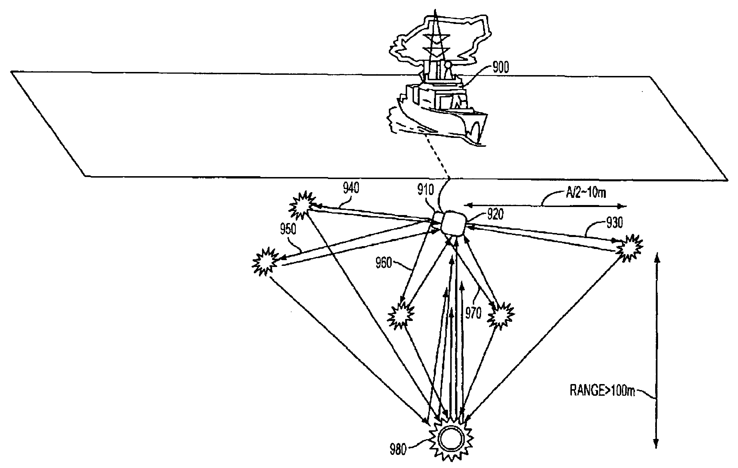
[0021]A method employing ultrashort pulse lasers to generate acoustic and optical sources to characterize the marine environment and underwater targets allows far more benefits than simply the creation of an acoustic pulse. The disclosed technology combines optical interrogation techniques with the previously-explored acoustic measurement. The optical techniques include the ability of ultrashort laser pulses to generate a white light continuum for imaging, as well as generate a spectral signature from laser-induced spectroscopy (LIBS) at the target surface. The optical measurements can also be time-gated to select only the return pulse from the desired target. This requires knowledge of the distance to the target, which can be determined from the acou

Problems solved by technology

Optical characterization can also be performed, but again typically requires large amounts of illumination energy, especially considering the stronger attenuation in the ocean of optical energy than acoustic energy.
There are several problems with illuminating the undersea environment with large amounts of energy.
From an environmental perspective, depositing large amounts of energy into the ocean can damage the sea life/environment; resulting in unwanted effects and repercussions.
The effectiveness of the employed techniques determines which waters can and cannot be mapped/characterized in advance, and once in a given environment, the ability to detect and characterize dangers ahead of a craft places constraints on speed and the ability to maneuver.
Targeted high-resolution acoustic imagery is often difficult to obtain in a complex environment, and optical characterization can be difficult or impossible to obtain with monochromatic sources and especially in turbid waters.
Identification of chemicals is often done through water sampling and chemical analysis, which is

Method used


Image

  • Acoustic and optical illumination technique for underwater charaterization of objects/environment
  • Acoustic and optical illumination technique for underwater charaterization of objects/environment
  • Acoustic and optical illumination technique for underwater charaterization of objects/environment

Examples


Embodiment Construction

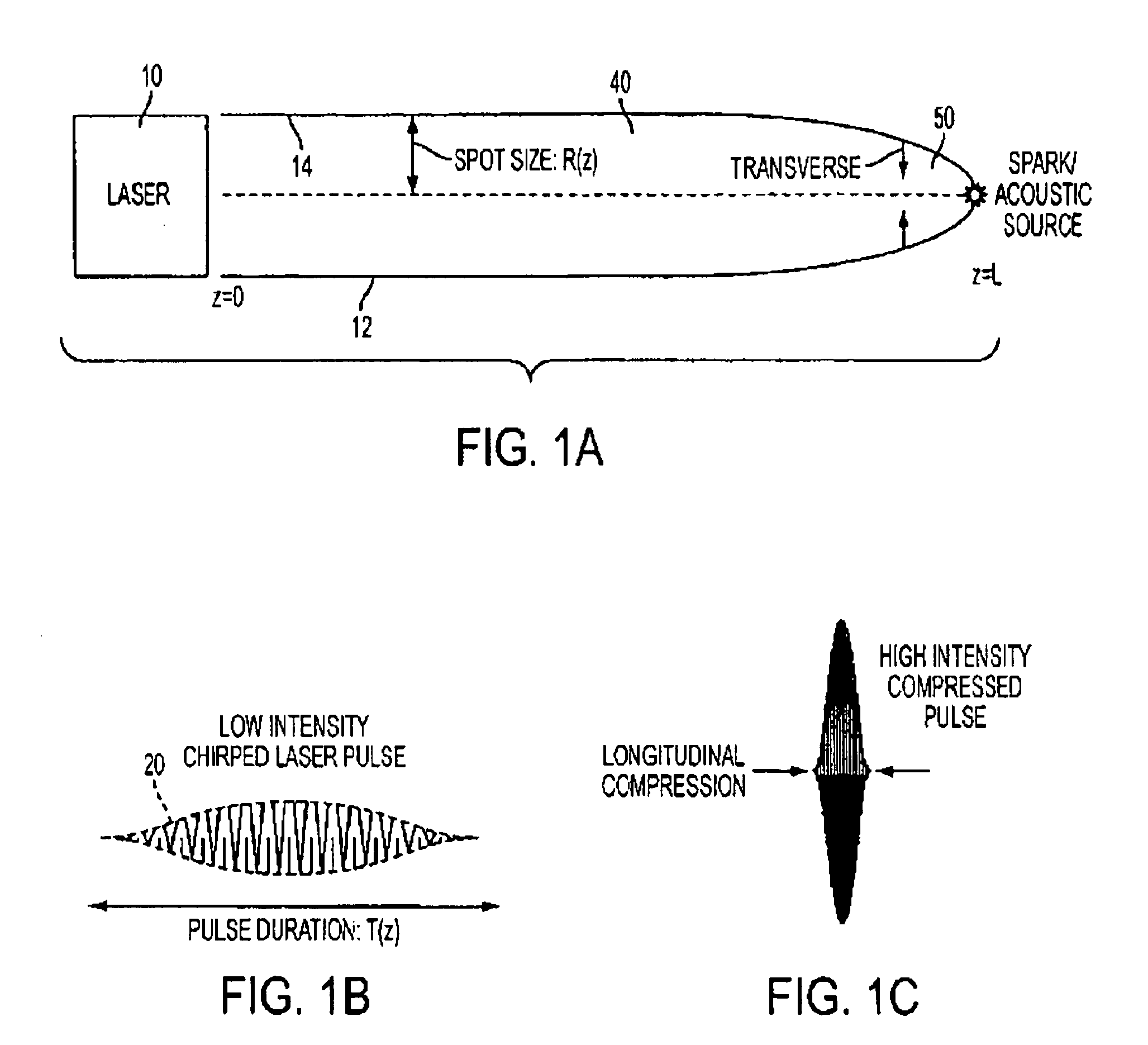
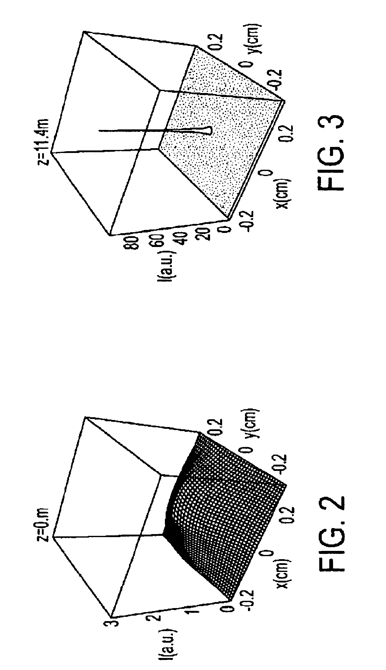
[0036]The method for remotely generating a combined acoustic and optical illumination source in water or another liquid having optical group velocity dispersion occurs through multiple mechanisms. The acoustic source is generated through a photo-acoustic sound generation technique, capable of generating an acoustic pulse at a predetermined remote underwater location many meters from the laser source. The remote acoustic generation occurs in two phases: 1) underwater laser pulse propagation and compression using some combination of group velocity dispersion-induced longitudinal compression, and transverse focusing due to the nonlinear refractive index of the liquid, and 2) laser-induced breakdown, heating and vaporization of a liquid volume, followed by rapid expansion and generation of a shock wave that can serve as a useful acoustic pulse. The concurrently generated optical illumination source arises through several potential mechanisms, including but not limited to: incoherent lin...


PUM


Abstract

The invention provides a method for acoustically and optically characterizing an immersed object of interest by generating a serial plurality of acoustic and optical illumination pulses through a liquid. In addition to the spectral analyses/imaging of objects/environment made possible by the white-light illumination, a target material can be ablated, generating an ionized plume to spectrally identify the target's constituent atoms.

Description

CROSS REFERENCE TO RELATED APPLICATION[0001]This application claims the benefit of priority from U.S. Provisional Patent Application No. 60 / 960,977, filed Oct. 23, 2007. The U.S. provisional application, in its entirety, is incorporated herein by reference.[0002]The following patents and patent applications are each incorporated herein by reference in their entirety:[0003]1) U.S. Pat. No. 6,527,221, which granted on Mar. 4, 2003, entitled “Shockwave Modification, Method and Apparatus and System;”[0004]2) U.S. Pat. No. 7,063,288, which granted on Jun. 20, 2006, entitled “Shockwave Modification, Method and System;”[0005]3) U.S. Pat. No. 7,121,511, which granted on Oct. 17, 2006, entitled “Shockwave Modification, Method and System;”[0006]4) U.S. patent application Ser. No. 11 / 288,425 filed on Nov. 29, 2005 and entitled “Shockwave Modification, Method and System;”[0007]5) U.S. patent application Ser. No. 11 / 540,964 filed on Oct. 2, 2006 and entitled “Shockwave Modification, Method and S...

Claims


Application Information

Patent Timeline
IPC IPC(8): G01N21/31G01N21/23G01N29/34
CPCG01N21/1702G01N21/21G01N21/6408G01N21/718G01N21/84G01N2021/1793G01N2201/0697G01B11/24G01N29/2418
Inventor KREMEYER, KEVIN
Owner KREMEYER KEVIN
Why Eureka
Try Eureka